Table of Contents
Advertisement
Quick Links
Advertisement
Table of Contents

Related Manuals for Frigicoll MIH22Q1N18


Summary of Contents for Frigicoll MIH22Q1N18
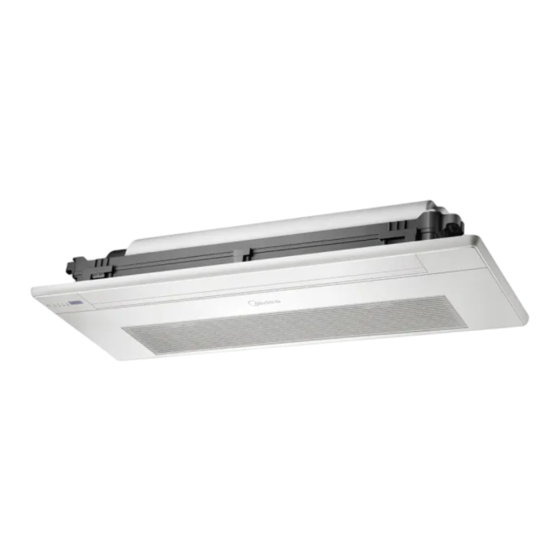
- Page 1 INSTALLATION AND OWNER'S MANUAL One Way Cassette MIH22Q1N18 (KCOF-22 DN5.0) MIH36Q1N18 (KCOF-36 DN5.0) MIH71Q1N18 (KCOF-71 DN5.0) Read this manual carefully before using the product, and keep it for future reference. All the pictures in this manual are for illustration purpose only.
-
Page 3: Table Of Contents
Contents About The Documentation About This Document / 1 Specific Installer Safety Instructions / 2 Safety Warning Safety Precautions / 3 Electric Safety Requirements / 4 About The Refrigerant / 5 Operation Operation Precautions / 8 Optimum Operation / 9 Symptoms That Are Not Faults / 10 Display Panel (Optional) / 13 Disposal / 13... -
Page 4: About The Documentation
About The Documentation About This Document Note Make sure that the user has the printed documentation and ask him/her to keep it for future reference. Target audience Authorised installers + end users Note This appliance is intended to be used by expert or trained users in shops, in light industry, and on farms, or for commercial and household use by lay persons. -
Page 5: Specific Installer Safety Instructions
Specific Installer Safety Instructions Please thoroughly read and ensure that you fully understand the safety precautions (including the signs and symbols) in this manual, and follow relevant instructions during use to prevent damage to health or property. Safety signs Danger Indicates a hazard with a high level of risk which, if not avoided, will result in serious injury. -
Page 6: Safety Warning
Safety Warning Warning Ensure Proper Grounding Professional Only Prohibition signs No Laying Inflammable No Strong Currents No Open Flame; Fire, No Acid or Alkali Materials Thing Open Ignition Source and Smoking Prohibited Safety Precautions Danger In the event of refrigerant leakage, smoking and open flames are prohibited. Disconnect the main power switch immediately, open windows to allow ventilation, keep away from the leakage point, and contact your local dealer or technical support to request a professional repair. -
Page 7: Electric Safety Requirements
Caution This appliance can be used by children aged from 8 years and above and persons with reduced physical, sensory or mental capabilities or lack of experience and knowledge if they have been given supervision or instruction concerning use of the appliance in a safe way and understand the hazards involved. Children shall not play with the appliance. -
Page 8: About The Refrigerant
About The Refrigerant Warning The following applies to R32 refrigerant systems. Prior to beginning work on systems containing flammable refrigerants, safety checks are necessary to ensure that the risk of ignition is minimized. For repair to the refrigerating system, the following precautions shall be complied with prior to conducting work on the system. - Page 9 During repairs to sealed components, all electrical supplies shall be disconnected from the equipment being worked upon prior to any removal of sealed covers, etc. If it is absolutely necessary to have an electrical supply to equipment during servicing, then a permanently operating form of leak detection shall be located at the most critical point to warn of a potentially hazardous situation.
- Page 10 i) Do not exceed the maximum working pressure of the cylinder, even temporarily. j) When the cylinders have been filled correctly and the process completed, make sure that the cylinders and the equipment are removed from site promptly and all isolation valves on the equipment are closed off. k) Recovered refrigerant shall not be charged into another refrigeration system unless it has been cleaned and checked.
-
Page 11: Operation
Operation Operation Precautions Warning If the unit will be not used for a long time, disconnect the main power switch. Otherwise, an accident may occur. The installation height of the air conditioner shall be at least 2.5m above the ground to avoid the following risks: 1. -
Page 12: Optimum Operation
Disposal: Do not dispose of this product as unsorted municipal waste. Collection of such waste separately for special treatment is necessary. Do not dispose of electrical appliances as unsorted municipal waste, use separate collection facilities. Contact your local government for information regarding the collection systems available. If electrical appliances are disposed of in landfills or dumps, hazardous substances can leak into the groundwater and get into the food chain, damaging your health and well-being. -
Page 13: Symptoms That Are Not Faults
Caution Long-term air output at a 30° angle may cause condensation on the surface of the louver. It is recommended to turn on the anti-condensation function through the wired controller to alleviate this situation. Operating Range Use the unit in the following temperature and humidity ranges for safe and effective operation. Indoor 16~32°C temperature... - Page 14 The following symptoms are not system malfunctions The following phenomena are normal during operation of the air conditioner. They can be solved according to the instructions below or do not need to be solved. The indoor unit emits white mist ...
- Page 15 In winter, the outdoor temperature is low, and heating effects may be decreased In heating mode, the air-conditioning system absorbs heat from the outdoor air and releases heat to the indoor side. When the outdoor temperature is low, less heat is released. This is the principle of heat pump.
-
Page 16: Disposal
Display Panel (Optional) Not all models can display Digital display area: display information keys and LED indicators. such as temperature, error code, and spot check information. Display functions: 1. In Standby mode, the main interface displays “---”. 2. When starting up in Cool or Heat mode, the main interface displays the set temperature. In Fan mode, the main interface displays the indoor temperature. -
Page 17: Installation
Installation Carefully read this manual before installing the indoor unit. Installation Precautions Qualification and Safety Regulation Requirements Warning Please carry out the installation according to local standards. Ask your local dealer or professionals to install the product. This unit must be installed by professional technicians with relevant specialized knowledge. Users MAY NOT install the unit themselves;... - Page 18 Before and after installation, exposing the unit to water or moisture will cause electrical short circuit. Do not store the unit in a humid basement or expose it to rain or water. Make sure the installation base and lifting are robust and reliable; Insecure installation of the base may cause the air conditioner to fall, leading to an accident.
- Page 19 Precautions for Carrying and Lifting the Air Conditioner Before carrying the air conditioner, determine the route that will be used to move it to the installation site. Do not unseal the air conditioner until it is moved to the installation site. When unpacking and moving the air conditioner, must hold the hanger seat and do not apply force to other parts, especially the refrigerant piping, drain pipe and plastic accessories, so as to avoid damaging the air conditioner and causing personal injury.
- Page 20 Keep the air-conditioning return air away from direct exposure to the sun in the room. The indoor unit should not be lifted in the places like load-bearing beams and columns that affect the structural safety of the house. The wired controller and the indoor unit should be in the same installation space; otherwise, the sampling point setting of the wired controller needs to be changed.
- Page 21 Layout Installation layout Panel (optional) Fresh air inlet Water pump Drainage outlet for water pump Water cover assembly Motor Gas pipe Liquid pipe Access hole *Power cable and earth wires *Communication line *Connection wires Wired controller (optional) Remote controller (optional) * To be purchased separately on site.
- Page 22 Product Dimensions (Unit: mm) D: Distance between lifting bolts E: Dimensions of unit F: Panel dimensions OD of water-outlet pipe connector (Φ25) O: Refrigerant piping connector (liquid side) Hanger rod installation P: Refrigerant piping connector (gas side) Hex nut (to adjust the level) Ceiling Panel Main body of air conditioner...
-
Page 23: Installation Materials
Installation Materials Accessories List of accessories Installation and Flare nut X 2 Drain pipe X 1 Cable tie X 10 Thermal insulation pipe Operation Manual X 1 For use in the installation Unavailable for units with a Used to tighten the drain of connecting pipe (the drain pump hose tightly to the drainage... - Page 24 Connecting pipe (Unit: mm) Piping Liquid side Gas side Capacity(kW) kW≤5.6 Φ6.35×0.75 Φ12.7×0.75 5.6<kW≤7.1 Φ9.52×0.75 Φ15.9×1.0 For connection of the indoor unit refrigerant system, it is recommended Remarks to use a soft connecting pipe (T2M), with the length selected according to the actual situation.
-
Page 25: Preparations Before Installation
Preparations Before Installation Unpacking Check B efore installation, check whether the packing materials are in good The red dot bulges condition, whether the accessories that come with the product are Sealing complete, whether the air conditioner is intact, whether the surfaces of the heat exchanger and other parts have become worn, and whether there are oil stains on the stop valve of the unit. - Page 26 Side view Note The air conditioner should be mounted at a height within the required range. Otherwise, it will not perform as expected. Return Air outlet air inlet Caution No obstacles (chandelier etc.) in front of the air outlet. Select a proper air supply angle range. (Unit: mm) Capacity(kW) kW≤3.6...
- Page 27 Determine the positions of the ceiling opening, the unit and the lifting bolts Make an opening according to the profile of the mounting cardboard. (Unit: mm) Bolt positioning dimension: D Size of opening in ceiling: C Capacity(kW) kW≤3.6 1100 1015 3.6<kW≤7.1 1290 1235...
- Page 28 When installing the air conditioner on a new ceiling, affix a piece of cardboard to the main body of the installed air conditioner for reference to determine the size, location, and center of the ceiling opening. Caution Evenly adjust the four hex nuts to make sure that the body of the air conditioner is level. When the air conditioner is to be fixed onto the ceiling with a frame: The horizontal distance of the overlapping part of the ceiling and decoration panel must be more than 10mm.
- Page 29 Cut the ceiling and verify that the lifting height is correct. 24 mm Caution After the ceiling is cut, remove the mounting cardboard. Keep the screws as you will need them for installing the panel. Caution Before connecting the indoor unit piping and wiring, connect the refrigerant piping, drainage pipe, remote controller wire (not required when a wireless remote controller is used), and the connection wire, power cable, and ground wire between the indoor unit and iutdoor unit (please refer to piping and wiring instructions) so that they can be connected to the indoor unit immediately after installation.
-
Page 30: Indoor Unit Installation
Indoor Unit Installation Warning Install the air conditioner in a location with sufficient strength to support the weight of the unit. Take reinforcement measures when necessary. The unit may fall and cause personal injury if the location is not strong enough. Unstable installation may cause the unit to fall and cause an accident. - Page 31 Installation of Lifting Bolts Refer to the following figure on installation using the lifting bolts. Sites with concrete slabs Sites with concrete slabs Use embedded bolts and pull bolts Directly set and use an angle iron for support. Lifting bolts Lifting bolts Angle iron for support...
- Page 32 Keep the unit level. Use a transparent hose to observe the water level (principle of communicating vessels) and verify the levelness of the unit in the depth direction. Use a transparent hose to observe water level (principle of communicating vessels) and verify the tilt angle of the unit in the length direction.
- Page 33 Toggle the buckle shown in the figure to remove the filter screen. Open the fan guide vane and remove the three cover plates for concealing screws. Keep the removed air grille, filter screen, and cover plates for concealing screws probably. Be careful not to lose them and protect them from dirt and scratches.
- Page 34 Electrical wiring of panel assembly: Open the electric control box cover of the air conditioner, and connect the control display connection terminal of the panel assembly and the motor connection terminal of the fan guide vane to the main control board of the air conditioner, as shown in the figure. Lead the 4-core cable on the panel through the cable...
- Page 35 Install screws One more screw is required for capacity 3.6<kW≤7.1. M4×22 screws (6 for capacity kW≤3.6; 7 for capacity 3.6<kW≤7.1), included in the accessory package Warning Make sure the cables connected to the panel and air conditioner are not clamped before you install the screws.
-
Page 36: Refrigerant Connecting Piping Installation
Install the filter screen and return air grille. Caution The panel should be installed in such a manner that its display faces towards the piping side of the air conditioner. After confirming that everything is correct, tighten the installation screws for the panel. Refrigerant Connecting Piping Installation When connect different series of outdoor units, the length and level differences of piping connections. - Page 37 The wrapped connecting pipe is plugged through the wall hole sleeve from the outdoor side and enters the indoor side. The pipes must be arranged carefully so as not to damage the piping. Outdoors Recommended Indoors through-wall direction Pipe Connection Steps Measure the required length of the connecting pipe.
- Page 38 Caution The bending angle should not exceed 90°; otherwise, wrinkles will be formed in the pipe, which can easily break. The bending radius should not be smaller than 3.5D (pipe diameter) and should be as large as possible to prevent the pipe from becoming flattened or crushed. When mechanically bending the pipe, the pipe bender inserted into the connecting pipe must be cleaned.
- Page 39 Handle Yoke Cone Connecting pipe Clamp handle Red arrow mark Nut fastening Align the connecting piping, firstly tighten most of the thread of the connecting nut by hand, and then use a wrench to tighten the last 1-2 turns of the thread as shown in the figure. The welding is done on site, and the bell mouth cannot be used indoors.(For IEC/EN 60335-2-40 except IEC 60335-2-40: 2018) The protective nut is a one-time part, it can not be reused.
- Page 40 Caution Depending on the installation conditions, excessive torque will damage the flared mouth, and too small torque cannot tighten the nut, which will cause refrigerant leakage. Please refer to the above table to determine the appropriate tightening torque. Refrigerant Piping Fixing Angle iron brackets or round steel hangers should be used for fixing.
- Page 41 Leak Detection The leak test must satisfy the specifications of EN378-2. To check for leaks: Vacuum leak test Evacuate the system from the liquid and gas piping to –100.7 kPa (–1.007 bar)(5 Torr absolute) for more than 2 hours. ...
-
Page 42: Drain Pipe Installation
Drain Pipe Installation Caution Before installation of the condensate pipeline, determine its direction and elevation to avoid intersection with other pipelines to ensure that the slope is straight. The highest point of the drain pipe should be equipped with a vent port to ensure the smooth drainage of condensate water, and the vent port must face downwards to prevent dirt from entering the pipe. - Page 43 Thermal insulation pipe PVC water drain pipe (outer diameter: 25mm) Drainage outlet for water pump There is a large gap between the The thermal thermal insulation insulation pipe is pipe and the unit, closely attached to resulting in thermal the unit. insulation failure.
- Page 44 The end of the drain pipe must be more than 50mm above the ground or from the base of the water drainage slot. In addition, do not submerge it in water. To drain the condensed water directly into a ditch, the water drain pipe must bend upwards to form a U-shaped water plug to stop odors from entering the room via the water drain pipe.
- Page 45 Water Drainage Test Before the test, make sure that the water drain piping is smooth, and check that each connection is properly sealed. Conduct the water drainage test in a new room before the ceiling is plastered. Rotate in the direction of arrow to unlock the test water cap The drain pipes for indoor units may use a PVC pipe...
-
Page 46: Electrical Connection
Electrical Connection Danger The power supply must be cut off before any electrical work is carried out. Do not conduct electrical work when the power is on; otherwise, it may cause serious personal injury. The air conditioning unit must be grounded reliably and must meet the requirements of the local country/ region. - Page 47 Electrical Characteristics Electric specifications of the indoor unit Capacity (kW) Frequency IFM power Voltage (V) Voltage (V) FLA (A) (Hz) input (W) 0.38 0.30 198~242 0.39 0.31 0.59 0.47 Notes: MCA: Min. Circuit Amps. (A), which is used to select the minimum circuit size to ensure safe operation over a long period of time.
- Page 48 Schematic figure of the main terminal blocks of main control board CN22 CN10 CN55 Terminals of remote M1 M2 X1 X2 D1(X) D2(Y) switch signal Terminals of communication line Power cable and earth Terminals of strong Terminals of line terminals current sterilization alarm signal module...
- Page 49 Weak current Strong current inlet inlet Communicati Power cable on line and and ground display box wire, etc. cable Caution Strong and weak current wires must be separated. Alarm signal output, strong current sterilization, and remote switch are custom or optional. Power supply cable connection ...
- Page 50 Do not press the power supply cables of the same wire diameter on the same side of the terminal. Do not use two power supply cables of different wire diameters for the same terminal blocks; otherwise, they can easily loosen due to uneven pressure and cause accidents, as shown in the figure below.
- Page 51 Power supply cable system connection Power supply cable system connection depends on the forms of communication between the indoor unit and outdoor unit. For the HyperLink (M1M2) communication form, indoor units are allowed to have independent power supplies. For other communication forms, indoor units should be provided with uniform power supplies. Master Communication wire outdoor unit...
- Page 52 Indoor units are provided with uniform power supply*, which are wired as follows: 1. HyperLink (M1M2) communication with the uniform power supply: Power supply for indoor unit L1+La+Ln ≤ 2000m Circuit breaker × × Communication wire Wire diameter: 0.75mm Power supply cable Distribution box Distribution box Master...
- Page 53 Caution When the indoor units are provided with a uniform power supply, if the indoor units in the same refrigerant system are V8 indoor units, then indoor units and outdoor unit can communicate either via HyperLink (M1M2) with a uniform power supply, or via P/Q. If some of the indoor units in the same refrigerant system are non-V8 series, then indoor units and outdoor unit can only communicate via P/Q/E communication.
- Page 54 Communication wiring connection Selection of communication method for indoor units Equipped with independently developed HyperLink (M1M2) communication, V8 series indoor units also preserve the previous RS-485 (PQE) communication method. They are compatible with non-V8 indoor units. Pay attention to the type of indoor unit before connecting communication wiring Please refer to the following table to select an appropriate communication method.
- Page 55 Caution Please select the communication wring according to the requirements in the above reference table. Use shielded cables for communication when strong magnetism or interference is present. On-site wiring must comply with the relevant regulations of the local country/region and must be completed by professionals.
- Page 56 Indoor unit and outdoor unit communication HyperLink (M1M2) communication (with independent power supply) Single unit: HyperLink (M1M2) communication is a new type of indoor unit and outdoor unit communication technology. When the indoor units are provided with independent power supplies, use 2×1.5mm communication cables.
- Page 57 Caution If the total length is less than or equal to 200m and the total number of indoor units is less than or equals to 10 sets, the electronic expansion valve in indoor unit can be powered and controlled by the master outdoor unit.
- Page 58 System: The HyperLink (M1M2) communication wring with a uniform power supply between indoor unit and outdoor unit can reach a length of up to 2000 meters, supporting any topology connection. The following figure shows a serial connection: Power supply for indoor unit Communication wire ×...
- Page 59 System: The maximum total length of the P/Q communication cable of the Indoor unit and outdoor unit can be up to 1200m, and can be connected in serial, as shown in the figure below: Power supply for indoor unit Communication wire ×...
- Page 60 Caution When P/Q or P/Q/E communication is used, the indoor units need to be powered uniformly. Either P/Q, P/Q/E communication or HyperLink (M1M2) communication can be selected. If it is required for indoor units to have independent power supplies, then HyperLink (M1M2) communication must be selected. Use only shielded cables for P/Q or P/Q/E communication.
- Page 61 D1D2 communication wring connection (limited to outdoor unit and system configuration) Achieving one-to-multiple and two-to-multiple functions of the indoor unit wired controller through D1D2 communication (a maximum of 16 sets) D1D2 communication is 485 communication. The one-to-more and two-to-more functions of the indoor unit wired controller can be achieved through D1D2 communication, as shown in the figure below: Indoor unit 1# Indoor unit 2#...
- Page 62 Alarm signal output, strong current sterilization connection (customized function) The alarm signal output and strong current sterilization power supply terminals are located on the main control board. The alarm signal output and strong current sterilization modules are connected to the power supply terminal with the bit number “CN22”...
-
Page 63: Error Codes
Error Codes Error Codes and Definitions In the following circumstances (warning failures excluded), please stop the air conditioner immediately, cut off the power switch and contact the local air conditioner customer service center. The error code is displayed on the display box and the wired controller display. Digital Error Error code... - Page 64 Digital Error Error code display Abnormal communication between the indoor unit and outdoor unit Abnormal communication between the indoor unit main control board and fan drive board Abnormal communication between the indoor unit and wired controller Abnormal communication between the indoor unit and Wi-Fi Kit Abnormal communication between the indoor unit main control board and display board Abnormal communication between the AHU Kit slave unit and master unit...
- Page 65 Digital Error Error code display The built-in room temperature sensor of the wired controller short-circuits or cuts off The wireless temperature sensor short-circuits or cuts off The external room temperature sensor short-circuits or cuts off Tcp (pre-cooled fresh air temperature sensor) short-circuits or cuts off Tph (pre-heated fresh air temperature sensor) short-circuits or cuts off TA (outlet air temperature sensor) short-circuits or cuts off Outlet air humidity sensor fault...
- Page 66 Digital Error Error code display Low bus voltage fault High bus voltage fault Phase current sample bias error Motor and indoor unit are unmatched IPM and indoor unit are unmatched Motor startup failure Motor blocking protection Speed control mode setting error Phase lack protection of motor Operating Status Codes and Definitions (Non-Error) Digital...
- Page 67 Spot Check Description Use the bi-directional communication wired controller (for example, WDC3-86S) to activate the spot check function in the following steps: On the main page, hold “ ” and “▲” for 2s to enter the query page. The wired controller displays Check No.
-
Page 68: Test Run
Test Run Before the Test Run, Make Sure That • Indoor units and the outdoor unit are properly installed. • The piping is correct, and the refrigerant piping system has been checked for leakage. • Piping length and the amount of refrigerant charged have been recorded. •... - Page 69 Check List To ensure a comfortable indoor environment, please run down through the list to check whether the installation of the air conditioner meets the requirements. Insert a “×” for Fail and a “√” for Pass. Check Result Check Item Check Criteria (Pass/Fail) Are the indoor units and outdoor units securely...
-
Page 70: Maintenance And Service
Maintenance and Service Safety Warning Warning For safety reasons, always turn off the air conditioner and turn off the power before cleaning the air conditioner. Do not disassemble or repair the air conditioner by yourself; otherwise, it may cause fire or other hazards. Only professional service personnel can carry out the maintenance. - Page 71 Procedure diagram Remove the air inlet grille. Hold and open the buckle at the return air inlet slowly, pull inward and press the filter buckle to remove the filter. Remove the filter. Note Only authorised installer or service agent can change and disassemble the filter. Any improper operations may cause electric shock or injuries due to touching rotating parts.
- Page 72 Cleaning Air Outlets and Exterior Panels Wipe the air outlet and panel with a dry cloth. If a stain is hard to remove, clean it with clean water or neutral detergent. Caution Do not use gasoline, benzene, volatile agents, decontamination powder or liquid insecticides. Otherwise, the air outlet or panel may become discolored or deformed.
-
Page 73: Service
Service Step to dismantle the drain pan The drain pan must first be removed during the maintenance of the internal unit assembly. Dismantle the drain pan according to the following schematic to prevent water leakage in the unit (Make sure there is no residual water in the drain pan before dismantle it). - Page 74 Step to dismantle the Motor and Fan Loosen the screws on the motor cover. Remove the plastic cover from the motor. Plastic cover Remove the motor to repair or replace it. Remove the fan. Motor Step to dismantle the Evaporator Follow the steps above to remove the panel, drain pan, motor, and fan.
- Page 75 Remove the evaporator. Evaporator Maintenance and Service...
- Page 76 16126000007907 V.B...
- Page 77 Maintenance and Service...
- Page 78 Maintenance and Service...
Need help?
Do you have a question about the MIH22Q1N18 and is the answer not in the manual?
Questions and answers