Advertisement
Quick Links
Manuel d'utilisation et d'entretien
(Notice originale)
Instruction and maintenance manual
(Translation of the original note)
Manual de utilización y mantenimiento
(Traducción de la información original)
Benutzer- und Wartungshandbuch
(Übersetzung der Original-Anleitung)
Gebruiks- en onderhoudshandleiding
(Vertaling van de oorspronkelijke handleiding)
Руководство по эксплуатации и
обслуживанию
(Nеревод с оригинального уведомления)
Kasutus-ja hooldusjuhend
(Originaaljuhendi tõlge)
Naudojimo ir priežiūros vadovas
(Versta iš originalo)
Lietošanas un apkopes rokasgrāmata
(Oriģinālās instrukcijas tulkojums)
Instrucţiunile privind siguranţa
(Traducere a instrucțiunilor originale)
ﺩﻟﻴﻞ ﺍﻻﺳﺘﺨﺪﺍﻡ ﻭﺍﻟﺼﻴﺎﻧﺔ
()ﺗﺮﺟﻤﺔ ﺍﻟﺪﻟﻴﻞ ﺍﻷﺻﻠﻲ
WELDARC
200 C5
220T C5
33522200001_2_1
04/2020
Advertisement

Related Manuals for Kohler WELDARC 200 C5


Summary of Contents for Kohler WELDARC 200 C5
- Page 1 Manuel d'utilisation et d’entretien (Notice originale) Instruction and maintenance manual (Translation of the original note) Manual de utilización y mantenimiento (Traducción de la información original) Benutzer- und Wartungshandbuch (Übersetzung der Original-Anleitung) Gebruiks- en onderhoudshandleiding (Vertaling van de oorspronkelijke handleiding) Руководство по эксплуатации и обслуживанию...
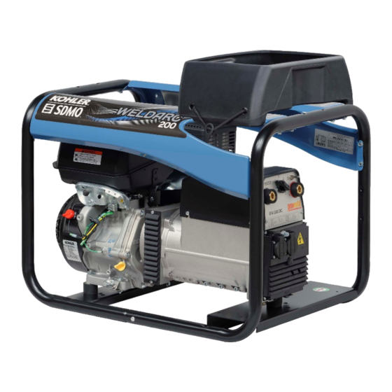
- Page 2 WELDARC 200 WELDARC 220 T...
- Page 4 FRANCE : 0.806.800.107 (Prix appel)
- Page 5 CONTENTS Section 1. Preface Section 6. Transporting and storing the welding set Section 2. Instructions and safety regulations (personal protection) Section 7. Repairing minor faults Section 3. Getting started with the welding set Section 8. Technical specifications Section 4. Using the welding set Section 9.
- Page 6 Serious risks of intoxication DANGER RISK OF POISONING DANGER OF DEATH (if appropriate) The carbon monoxide present in the exhaust gas may lead to death by inhalation if the concentration levels in the atmosphere are too high. Always use the unit in a well ventilated area where the gases cannot accumulate. For safety reasons and for correct operation of the unit, correct ventilation is essential (risk of poisoning, engine overheating and accidents involving, or damage to, the surrounding equipment and property).
- Page 7 2.7.4 Connection and choice of cables For all connections, use flexible, strong rubber-sheathed cables which comply with standard IEC 60245-4 or equivalent cables, and ensure that these are kept in perfect condition. Only use one item of class I electrical equipment per socket and connect up equipment using a cable equipped with a PE protective conductor (green/yellow);...
- Page 8 2.10.2 Fire risks when welding RISK OF FIRE DANGER DANGER OF DEATH Before welding: Remove any combustible substances from your pockets and check that the protective clothing you are wearing is not soiled. Connect the cable to the part to be welded as close as possible to the welding zone.
- Page 9 Section 3. Getting started with the welding set Key to illustrations The cover illustrations can be used to identify the various components of the unit. The procedures in the manual refer to these illustrations using letters and numbers as identifiers: "A1" refers to the number 1 on figure A. Earth terminal Starter-take-up reel handle Air filter cover...
- Page 10 Checking the engine oil level and topping up If the unit has been used, leave to cool for at least 30 minutes Remove the oil dipstick/filler plug (A2-B1) by unscrewing it, and wipe the dipstick. Insert the oil dipstick/filler plug in the filler neck (B2) without tightening it, then take it out again. Visually check the level: it must be between the upper limit (B5) and lower limit (B4) on the dipstick.
- Page 11 Using the electricity supplied Allow the unit speed to stabilize and the temperature to rise (approx. 3 to 5 min.). Connect the equipment to be used to the electrical sockets (A14) on the unit. For France only: Our units are fitted with sockets where the earthing contact is made using side tabs. In exceptional cases where the equipment is only fitted with an earthing pin, use an adaptor.
- Page 12 5.3.2 Clean the screen filter If fitted: close the fuel tap. Unscrew the fuel tank cap (A3). Remove the screen filter (A4) located inside the fuel tank. With a low-pressure dry air gun, blow air through the screen filter, from the outside inwards. Rinse it using clean fuel and dry it.
- Page 13 Section 6. Transporting and storing the welding set Transport and handling conditions The unit should be handled gently and sudden movements should be avoided. Ensure that the place where it is to be stored or used is carefully prepared beforehand. Before any fixed installation on a trailer or inside a vehicle, consult one of our approved agents. Before transporting the unit, take the following necessary precautions: Check that the routes to be used are smooth and drivable.
- Page 14 Diagnostics for welding problems Welding problems: Possible causes: Solutions to be applied: Low welding output. The settings for the controls are correct. Check the settings for the controls. Have the unit checked by one of our The unit speed is correct. agents*.
- Page 15 Current amperage Serial numbers will be required when requesting troubleshooting advice or spare parts. For your records, please enter the unit and engine serial numbers below. Engine manufacturer:(e.g. Engine serial number: (e.g Kohler (SERIAL Unit serial number: Kohler) NO. 4001200908)) ……/…………..
- Page 16 We, SDMO Industries - 270 rue de Kerervern, 29490 GUIPAVAS/CS 40047, 29801 BREST CEDEX 9 – France, hereby declare under our sole responsibility that the following generators: Equipment Make: Trade name: Type: Serial numbers: description: WELDARC 200 C5 3499231004111 09-2019-00000000-000 Welding set KOHLER-SDMO 52-2026-99999999-999 WELDARC 220 T C5 3499231004128 1.
- Page 17 Section 9. Conditions of warranty COMMERCIAL WARRANTY Your unit is covered by a commercial warranty granted by SDMO Industries. This warranty must be applied by the distributor from which you purchased your unit, in accordance with the following provisions: TERM: The warranty for your unit is valid for a period or 36 months or 2000 operating hours, from the date of purchase.
- Page 18 LEGAL GUARANTEES Information for the consumer, who is defined as any individual acting for purposes outside of his or her trade, business, craft or profession. SDMO Industries is liable for any conformity issues with your unit under the conditions set out in article L. 211-4 and following of the Consumer Code and for hidden defects in the sold item under the conditions set out in articles 1641 and following of the civil code.
Need help?
Do you have a question about the WELDARC 200 C5 and is the answer not in the manual?
Questions and answers