Table of Contents
Advertisement
Quick Links
GNS 401 StarterKit
manual
confidential information
manual
The GNS 401 Starter Kit has been designed to support developers during
design-in of the GNS 401 GPS stand alone receiver solution.
The examples are shown as block diagrams to explain the approaches. Reference Layouts are included
whenever needed at the GNS forum Link:
www.forum.gns-gmbh.com
.
GNS Global Navigation Systems GmbH
Adenauerstrasse 18
D – 52146 Würselen
Germany
www.gns-gmbh.com
info@gns-gmbh.com
1
© GNS-GmbH 2013
V 0.11, Jan. 18th 2013
Advertisement
Table of Contents

Related Manuals for GNS 401 Starter Kit


Summary of Contents for GNS 401 Starter Kit
- Page 1 The GNS 401 Starter Kit has been designed to support developers during design-in of the GNS 401 GPS stand alone receiver solution. The examples are shown as block diagrams to explain the approaches. Reference Layouts are included whenever needed at the GNS forum Link: www.forum.gns-gmbh.com...
-
Page 2: Introduction
Introduction This manual shows, how to connect the GNS 401 Starter Kit to a PC in order to verify GNS401 module performance and test supported features. For technical specification, please refer to the GNS401 datasheet. GNS 401 is one of the smallest GPS receiver module based on the MT3329 single chip solutions, available with a finely tuned, high-sensitivity patch ceramic antenna. -
Page 3: Table Of Contents
Index Introduction ..........................2 1 Description of the GNS 401 StarterKit Hardware ..............4 2 GNS 401 StarterKit Board Layout ..................5 3 GNS 401 StarterKit Board Block Diagram ................6 Getting started …......................6 4 GPS viewer software ......................10 View Menu “Skyplot”... -
Page 4: Description Of The Gns 401 Starterkit Hardware
1 Description of the GNS 401 StarterKit Hardware FEATURES Small evaluation board designed for verification of GNS 401 module GPS performance parameters Small evaluation board designed for easy implementation to MCU controlled applications GPS-fix LED indicator PC connection via USB... -
Page 5: Gns 401 Starterkit Board Layout
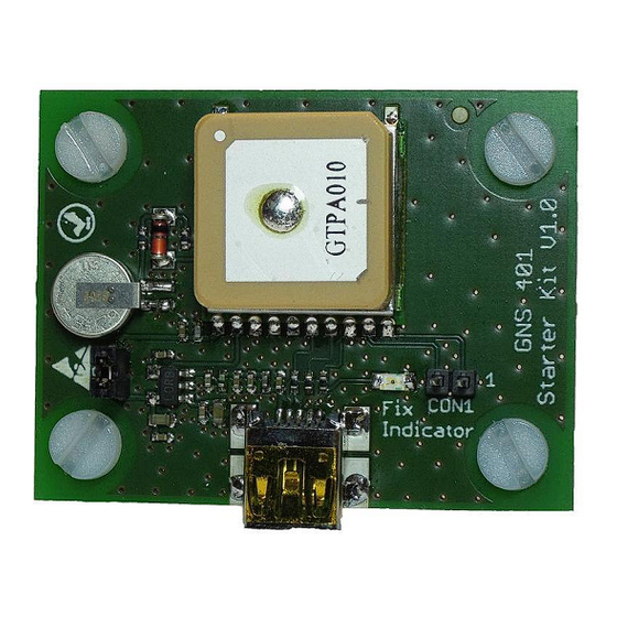
GNS 401 StarterKit manual confidential information manual 2 GNS 401 StarterKit Board Layout GNS401 Battery Power supply Fix indicator jumper Con1: UART RX/TX mini USB connector Description of LED status indicator: LED status indicator Comment blinking GPS engine is in acquisition mode. Almanac- and Ephemeris- data will be received. -
Page 6: Gns 401 Starterkit Board Block Diagram
2. Copy the six files from the \Driver folder to a PC folder of your choice. 3. GNS 401 Starter Kit will be connected to the PC via a virtual COM-Port with USB. This conversion is performed by an onboard chip. - Page 7 GNS 401 StarterKit manual confidential information manual 5. The VCP USB driver is not ready to use at this state. 6. Connect the Starter Kit to your PC by using the USB- to miniUSB cable. This will power up the Starter Kit (shown by the blinking green LED fix indicator) and establish the active state.
- Page 8 GNS 401 StarterKit manual confidential information manual 11. Choose “Hardware” tab and select “Device Manager” 12. Select “Ports (COM&LPT)” and notice the “GPS USB Serial Interface Driver” number © GNS-GmbH 2013 V 0.11, Jan. 18th 2013...
- Page 9 13. Start your preferred NMEA-Viewer software (for example: Visual GPS, free NMEA-Viewer, Link: http://www.visualgps.net/VisualGPS/default.htm ) to visualize the NMEA-protocol data and connect COM-Port using the default data rate of the GNS 401 module of “9600Baud”. © GNS-GmbH 2013 V 0.11, Jan. 18th 2013...
-
Page 10: Gps Viewer Software
GNS 401 StarterKit manual confidential information manual 4 GPS viewer software The GPS viewer software is a very easy-to-use demonstration and testing program. It allows to test and to verify the performance of the module itself as well as the performance of GPS antennas. - Page 11 GNS 401 StarterKit manual confidential information manual Description of “Skyplot” controls: Control Comment Satellite display This control shows all satellites that are currently in view. The numbers on top of the bars show the C/N (code-to-noise) ratio. The color of the bar is dark blue, if the SV is used for the navigation solution.
-
Page 12: View Menu "Nmea
GNS 401 StarterKit manual confidential information manual View Menu “NMEA” Com-port baud rate DGPS mode Geodetic Logs NMEA and datum communication data to a file Clears communication window Communication window © GNS-GmbH 2013 V 0.11, Jan. 18th 2013... - Page 13 GNS 401 StarterKit manual confidential information manual Description of “NMEA” controls: Control Comment NMEA output settings This control allows to select the output NMEA sentences based on the NMEA data output rate of 1Hz. For example: GGL (0); RMC (1); VTG(1);...
-
Page 14: View Menu "Skyplot" Restart Mode Selection
GNS 401 StarterKit manual confidential information manual View Menu “Skyplot” restart mode selection Four GPS-Core start-up modes, factory reset, cold start, warm start and hot start, are selectable to perform receiver restarts. The start-up condition data for the GPS engine is injected as referred to the following table. -
Page 15: View Menu "Advanced Functions
The GPS viewer software provides additionally test functions by pressing “Ctrl+Alt+S” keys at the same time. New tabs will be displayed. For GNS 401 testing, the function “EPO” (Assisted GPS, A-GPS) is only supported. All other functions were supported by using the GNS 601 based upon the MT3339 chip. -
Page 16: Gns 401 Configuration
5 GNS 401 configuration In all cases, where a UART or USB connection to a PC is available, the GNS 401 offers a comfortable way to reprogram the firmware options or settings using the bidirectional NMEA command interface. Note: Removing the power of the GPS device will effect that any modified setting will be lost and reset to factory default settings. -
Page 17: Transmitting Pmtk Commands Via Hyperterminal
GNS 401 StarterKit manual confidential information manual Transmitting PMTK commands via HyperTerminal Example: Operating System: Windows XP 1. Execute HyperTerminal, creating a COM port called, for example: test. 2. Assign the virtual COM-Port number by executing “Windows Start Button” and select “Control panel”. - Page 18 GNS 401 StarterKit manual confidential information manual 3. Select “system”. 4. Choose “Hardware” tab and select “Device Manager”. © GNS-GmbH 2013 V 0.11, Jan. 18th 2013...
- Page 19 GNS 401 StarterKit manual confidential information manual 5. Select “Ports (COM&LPT)” and notice the “USB Serial Port” or “COM Port” number, where the GPS device is connected to. Here: USB Serial Port (COM 3). 6. Select the COM port at the “Connect To” windows, using the drop down menu.
- Page 20 GNS 401 StarterKit manual confidential information manual 7. After successfully connection with GPS device, the NMEA messages will be displayed on the window. Please choose “File” -> “Properties”. 8. Please select the “Settings” tab and click “ASCII Setup” to check the ASCII sending settings and confirm.
- Page 21 GNS 401 StarterKit manual confidential information manual 9. Use “notepad” to edit the $PMTK command, adding “*” and the checksum value. Save this file as “txt”-file, here “b.txt”. 10. Choose at “Transfer” -> “Send Text File”. The pop-up window will request the file you want to transfer.
- Page 22 GNS 401 StarterKit manual confidential information manual 11. At the HyperTerminal the result can be confirmed. © GNS-GmbH 2013 V 0.11, Jan. 18th 2013...
-
Page 23: Gns 401 Starterkit Hardware
GNS 401 StarterKit manual confidential information manual 6 GNS 401 StarterKit Hardware Assembly Drawing Top Side © GNS-GmbH 2013 V 0.11, Jan. 18th 2013... -
Page 24: Gns 401 Starterkit Schematic
GNS 401 StarterKit manual confidential information manual GNS 401 StarterKit Schematic © GNS-GmbH 2013 V 0.11, Jan. 18th 2013... -
Page 25: Gns 401 Starterkit Bill Of Material
GNS 401 StarterKit manual confidential information manual GNS 401 StarterKit Bill Of Material device value, type board reference Battery Battery 621FE BAT0101 LED green CHIPLED-0805 LED0101 Connector/Jumper PINHD-1X2_RM2.00 CON1, JP1 Diode BAS85 D0101 MiniUSB connector MiniUSB connector MINIUSB GPS receiver... -
Page 26: Ordering Information
This product is free of environmental hazardous substances and complies to 2002/95/EC. (RoHS directive). 9 RELATED DOCUMENTS Type description Available from GNS 401 data sheet Data sheet for GNS 401 receiver http://www.forum.gns-gmbh.com Description of all available NMEA NMEAcommandInterface commands for chip settings and feature http://www.forum.gns-gmbh.com manual...
Need help?
Do you have a question about the 401 Starter Kit and is the answer not in the manual?
Questions and answers