Table of Contents
Advertisement
Quick Links
SPLIT-TYPE AIR CONDITIONER
Owner's Manual &
Installation Manual
IMPORTANT NOTE:
Read this manual carefully before installing or operating
•
your new air conditioning unit. Make sure to save this
manual for future reference.
Please check the applicable models, technicaldata, F-GAS and
•
manufacturer information from the "Owner's Manual - Product
Fiche " in the packaging of the outdoor unit.
(European Union products only)
Advertisement
Table of Contents

Related Manuals for Carrier Ahi XPower 42QFD


Summary of Contents for Carrier Ahi XPower 42QFD
- Page 1 SPLIT-TYPE AIR CONDITIONER Owner’s Manual & Installation Manual IMPORTANT NOTE: Read this manual carefully before installing or operating • your new air conditioning unit. Make sure to save this manual for future reference. Please check the applicable models, technicaldata, F-GAS and •...
-
Page 2: Table Of Contents
Table of Contents Operating Instructions Safety Precautions ..........04 Indoor Unit Parts and Major Functions ..09 SAFETY FIRST Manual Operations ..........11 Care and Maintenance ......14 Troubleshooting ......16 Installation Instructions Accessories ..........Installation Overview ....... Indoor Unit Installation .... - Page 3 Outdoor Unit Installation ......26 Drainpipe Installation .......29 Refrigerant Piping Connection ..30 Wiring ..............33 Air Evacuation ..........35 Test Run .................37 European Disposal Guidelines ....... 38 Information servicing ..........39 Caution : Risk of fire (for R32/R290 refrigerant only ) WARNING: Servicing shall only be performed as recommended by the equipment manufacturer.
-
Page 4: Safety Precautions
Safety Precautions Thank you for purchasing this air conditioner. This manual will provide you with information on how to operate, maintain, and troubleshoot your air conditioner. Following the instructions will ensure the proper function and extended lifespan of your unit. Read Safety Precautions Before Installation Incorrect installation due to ignoring instructions can cause serious damage or injury. - Page 5 WARNING 15. This appliance can be used by children aged from 8 years and above and persons with reduced physical, sensory or mental capabilities or lack of experience and knowledge if they have been given supervision or instruction concerning use of the appliance in a safe way and understand the hazards involved.
- Page 6 CLEANING AND MAINTENANCE WARNINGS 2. Do not clean the air conditioner with excessive amounts of water. 3. Do not clean the air conditioner with combustible cleaning agents. Combustible cleaning agents can cause re or deformation. Turn off the device and pull the plug before cleaning. Failure to do so can cause electrical shock.
- Page 7 CAUTION If the air conditioner is used together with other heating devices, thoroughly ventilate the room to avoid oxygen de ciency. DO NOT climb onto or place objects on top of the outdoor unit. DO NOT operate the air conditioner when using fumigant insecticides. The chemicals may become layered with the unit and endanger those who are hypersensitive to chemicals.
- Page 8 Cautions for using R32/R290 refrigerant onnecting piping(when connecting indoors). Use of pipes, areless nut or are nuts other than speci ed, may cause product malfunction, burst piping, or injury due to high internal pressure of the refrigerant cycle caused by any in ow air. Appliance shall be installed, operated and stored in a room with a oor area larger than X m²...
-
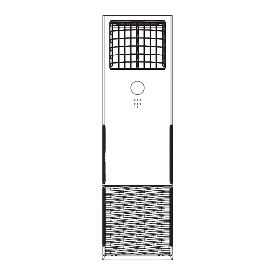
Page 9: Indoor Unit Parts And Major Functions
Indoor Unit Parts And Major Functions Unit Parts Air outlet Display panel Air inlet Fig. 2.1 Operating Conditions Use the system under the following temperatures for safe and effective operation. If the air conditioner is used under different conditions, it may malfunction or become less ef cient. Inverter Split Type •... - Page 10 Features Auto-Restart Default Setting When the air conditioner restarts after a power In case of power failure, the system will failure, it will default to the factory settings immediately stop. To restart the unit, press the ON/OFF button on the remote control. If the (AUTO mode, AUTO fan, 24°C (76°F)).
-
Page 11: Manual Operations
Manual Operations The display panel on the indoor unit can be used to operate the unit in cases when the remote control has been misplaced or is out of batteries. Auto operation Cooling operation Room Temp/Set Temp/Set Timer Dry operation display Heating operation Fan speed... - Page 12 Avoid button: 1. In any mode of boot, press the button to turn on the function. 2. Press “ ” , “ ”, “ ” close this function. Power button: Operation starts when this button is pressed and stops when you press the button again.
- Page 13 LOCK FEATURE: The lock feature is activated by pressing down and holding the fan speed and swing buttons simultaneously for a period of one second. This feature is available both when the unit is turned on or off. The rst time these buttons are pressed, the unit locks and all other buttons on the unit are disabled (apart from the unlock button).
-
Page 14: Care And Maintenance
Care And Maintenance Safety Precautions How To Clean The Air Filter Contact an authorized service technician The lter prevents dust and other particles from • for repair or maintenance. Improper repair entering the indoor unit. Dust buildup can reduce and maintenance may cause water leakage, the ef ciency of the air conditioner. - Page 15 4. Remove the air lter. Repairing Refrigerant Leaks 5. Clean the air lter by vacuuming the surface or washing it in warm water with mild WARNING detergent. A. If using a vacuum cleaner, the inlet side If the refrigerant leaks, turn off the air •...
-
Page 16: Troubleshooting
Troubleshooting CAUTIONS If one of the following conditions occurs, switch off the power supply immediately and contact your dealer for further assistance. • The operation light continues to ash rapidly after the unit has been restarted. The remote control buttons do not work. •... - Page 17 Problem Possible Causes Dust is emitted from The unit may accumulate dust during extended periods of non-use, which either the indoor or will be emitted when the unit is turned on. This can be mitigated by covering outdoor unit the unit during long periods of inactivity. The unit may absorb odors from the environment (such as furniture, cooking, The unit emits a cigarettes, etc.) which will be emitted during operations.
- Page 18 Error Codes Inverter Split Type • Error Number Cause Code Indoor EEPROM error Indoor and outdoor communication failure Indoor fan speed malfunction Indoor room temperature sensor open circuit or short circuit Evaporator coil temperature sensor open circuit or short circuit Refrigerant leakage detection malfunction Communication malfunction between two indoor units (for twins model) Other malfunction of twins model...
- Page 19 Fixed-speed Type • Error Cause Number Code Indoor EEPROM error Indoor and outdoor communication failure Dc fan stall failure T1sensor error T2sensor error Display board and main control communication failure Refrigerant leakage fault The compressor low pressure failure T4sensor error T3sensor error Power failure or lack of phase phase sequence reverse fault Heating the cold wind off the indoor fan...
-
Page 20: Accessories
Accessories The air conditioning system comes with the following accessories. Use all of the installation parts and accessories to install the air conditioner. Improper installation may result in water leakage, electrical shock and re, or equipment failure. Name Shape Quantity Indoor unit Self-tapping screw 3.9×25 installation... -
Page 21: Installation Overview
Installation Overview INSTALLATION ORDER Install the indoor unit Install the outdoor unit Install the drainpipe (Page 22) (Page 26) (Page 29) Evacuate the refrigeration system Connect the wires Connect the refrigerant pipes (Page 35) (Page 33) (Page 30) Perform a test run (Page 37) Page 21... -
Page 22: Indoor Unit Installation
Indoor Unit Installation Indoor Unit Parts Fig. 8.1 Outdoor unit Indoor unit Air outlet Drain pipe, vent pipe Operation panel Connection cable Horizontal air ow control louver Connection pipe Vertical air ow control louver Refrigerant pipe port Air inlet(2 sides) Air outlet NOTE ON ILLUSTRATIONS Illustrations in this manual are for explanatory purposes. - Page 23 DO NOT install unit in the following Indoor Unit Installation Instructions locations: Near any source of heat, steam, or PRIOR TO INSTALLATION combustible gas Before installing the indoor unit, refer to the Near ammable items such as curtains or label on the product box to make sure that the clothing model number of the indoor unit matches the Near any obstacle that might block air...
- Page 24 Step 2: Unfastening the operation panel and Step 3. Remove the fasteners from the roller (only found on selected models) 1. Check to see whether the roller on the indoor 1. Open the packaging and take out the indoor unit has any fasteners holding it in place and unit.
- Page 25 Use a knife to cut a small hole by following the Pipe/wire-hole position on back side markings on the ratproof board. (See Fig. 8.6) Insert the ratproof board into the unit and hold it in place tightly. Then attach the ratproof Refrigerant/drain board into the hole Pipe hole...
- Page 26 Outdoor Unit Installation The area must be free of combustible gases √ Outdoor Unit Installation Instructions and chemicals. √ The pipe length between the outdoor and Step 1: Select installation location. indoor unit may not exceed the maximum The outdoor unit should be installed in the allowable pipe length.
- Page 27 Outdoor Unit Mounting Dimensions Outdoor Unit Dimentsion (mm) Mounting Dimentsion (mm) The mounting dimensions vary among different outdoor units. The fixing bolt head diameter should be more than 12mm. The minimum distance between the NOTE: outdoor unit and walls described in the installation guide does not apply to airtight rooms.
- Page 28 Base pan hole of outdoor unit Seal Seal Drain joint Fig. 9.6 Fig. 9.7 Drain Joint Installation Notes On Drilling Hole In Wall You must drill a hole in the wall for the If the drain joint comes with a rubber seal refrigerant piping, and the signal cable that will (see Fig.
- Page 29 Drainpipe Installation The drainpipe is used to drain water from the 4. After the Drain Pipe has been connected, please check if the water drains out of the unit. Improper installation may cause unit and pipe ef ciently and has no leakage. property damage.
-
Page 30: Refrigerant Piping Connection
Refrigerant Piping Connection Step1: Cut pipes Safety Precautions When preparing refrigerant pipes, take extra care to cut and are them properly. This will ensure ef cient operation and minimize the WARNING need for future maintenance. • All eld piping must be completed by a 1. - Page 31 Step 3: Flare pipe ends Table 11.1: PIPING EXTENSION BEYOND FLARE FORM Proper aring is essential to achieve an airtight seal. Pipe Tightening Flare dimension (A) Flare shape 1. After removing burrs from cut pipe, seal torque (Unit: mm/Inch) gauge Min.
- Page 32 7. Thread this pipeline through the wall and connect it to the outdoor unit. 8. Insulate all the piping, including the valves of the outdoor unit. 9. Open the stop valves of the outdoor unit to start the ow of the refrigerant between the indoor and outdoor unit.
-
Page 33: Wiring
Wiring Follow these instructions to prevent distortion Safety Precautions when the compressor starts: WARNING • The unit must be connected to the main outlet. Normally, the power supply must • Be sure to disconnect the power supply have a low output impedance of 32 ohms. before working on the unit. - Page 34 Table 12.2: Other World Regions Indoor Unit Wiring Rated Current of Nominal Cross-Sectional 1. Prepare the cable for connection Appliance (A) Area (mm²) a. Using wire strippers, strip the rubber jacket 0.75 from both ends of the signal cable to reveal about 15cm (5.9”) of the wire.
-
Page 35: Air Evacuation
Air Evacuation 4. Turn on the vacuum pump to evacuate the Safety Precautions system. 5. Run the vacuum for at least 15 minutes, or until the Compound Meter reads -76cmHG CAUTION (-1x10⁵Pa). 6. Close the Low Pressure side of the manifold •... - Page 36 Note On Adding Refrigerant CAUTION • Refrigerant charging must be performed after wiring, vacuuming, and the leak testing. DO NOT exceed the maximum allowable quantity of refrigerant or overcharge the system. • Doing so can damage the unit or impact it’s functioning. •...
-
Page 37: Test Run
Test Run f. Check to see that the drainage system is Before Test Run unimpeded and draining smoothly. A test run must be performed after the entire g. Ensure there is no vibration or abnormal system has been completely installed. Con rm noise during operation. -
Page 38: European Disposal Guidelines
European Disposal Guidelines Users in European Countries may be required to properly dispose of this unit. This appliance contains refrigerant and other potentially hazardous materials. When disposing of this appliance, the law requires special collection and treatment. DO NOT dispose of this product as household waste or unsorted municipal waste. - Page 39 Information Servicing (Required for the units adopt R32/R290 Refrigerant only) 1. Checks to the area Prior to beginning work on systems containing ammable refrigerants, safety checks are necessary to ensure that the risk of ignition is minimised. For repair to the refrigerating system, the following precautions shall be complied with prior to conducting work on the system.
- Page 40 the charge size is in accordance with the room size within which the refrigerant containing parts are installed; the ventilation machinery and outlets are operating adequately and are not obstructed; if an indirect refrigerating circuit is being used, the secondary circuits shall be checked for the presence of refrigerant;...
- Page 41 12. Cabling Check that cabling will not be subject to wear, corrosion, excessive pressure, vibration, sharp edges or any other adverse environmental effects. The check shall also take into account the effects of aging or continual vibration from sources such as compressors or fans. Under no circumstances shall potential sources of ignition be used in the searching for or detection of refrigerant leaks.
- Page 42 16. Charging procedures In addition to conventional charging procedures, the following requirements shall be followed: Ensure that contamination of different refrigerants does not occur when using charging equipment. Hoses or lines shall be as short as possible to minimize the amount of refrigerant contained in them.
- Page 43 19. Recovery When removing refrigerant from a system, either for service or decommissioning, it is recommended good practice that all refrigerants are removed safely. When tranferring refrigerant into cylinders, ensure that only appropriate refrigerant recovery cylinders are employed. Ensure that the correct numbers of cylinders for holding the total system charge are available.
Need help?
Do you have a question about the Ahi XPower 42QFD and is the answer not in the manual?
Questions and answers