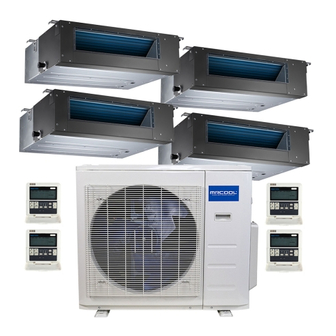
MrCool Olympus Series Install Manual
Mid-static duct air handler
Hide thumbs
Also See for Olympus Series:
- Installation & owner's manual (55 pages) ,
- Installation manual (39 pages) ,
- User manual (27 pages)
Advertisement
Quick Links
Please read this manual carefully before installation and keep it for future reference.
Wiring Control
Install Manual
Olympus Series
Mid-Static Duct Air Handler
(36K Models)
Please keep this manual where the operator can easily find it.
Inside you will find helpful hints on how to use and maintain your
unit properly.
For more info visit www.mrcool.com
Advertisement

Summary of Contents for MrCool Olympus Series
- Page 1 Install Manual Olympus Series Mid-Static Duct Air Handler (36K Models) Please keep this manual where the operator can easily find it. Inside you will find helpful hints on how to use and maintain your unit properly. For more info visit www.mrcool.com...
- Page 2 For more info visit www.mrcool.com...
- Page 3 Table of Contents Wall-Mounted Remote Control Wiring........1 Wall-Mounted Remote Control Installation......6 For more info visit www.mrcool.com...
- Page 4 DO NOT connect a 220V or 380V cable to the circuit loop. • Make sure that configured tubes are 12-20in (30-50cm) or more apart. • DO NOT employ an ohmmeter to detect the insulation after wiring the remote control. For more info visit www.mrcool.com...
- Page 5 Fig. 1 1.Wiring diagram Refer to the following diagram to wire the wall-mounted remote control to the indoor unit. Wire Joint, 5p Infrared Pipe 5-Core Shield Cable Indoor Unit Switch Board Indoor Unit Fig. 2 For more info visit www.mrcool.com...
- Page 6 Then connect the other side of the connecting cable to the remote control. The connective wires group 5-core wire Front grille Fig. 3 NOTE: Be sure to reserve a length of the connecting wire for periodic maintenance. For more info visit www.mrcool.com...
- Page 7 Use the trap and putty to seal the wires. Putty Trap Putty Putty Trap Trap Fig. 4 a. For exposed mounting, cut holes on three of the sides according to Fig. 5. b. For shielded wiring, please refer to Fig. 6. For more info visit www.mrcool.com...
- Page 8 Cut three holes for wire outlet Fig. 5 Embedded switch box wiring Wiring through the wall Wall hole and wiring hole Wiring hole Diameter of wall hole: Φ 2cm Fig. 6 For more info visit www.mrcool.com...
- Page 9 WARNING DO NOT operate the unit with wet hands, as this could lead to electrical shock. Remote Control Dimensions 4.7in 0.8in 0.5in (120mm) (21mm) (13.1mm) 0.7in (19.5mm) 4.7in 3.3in (120mm) (85.5mm) 1.9in (50mm) Fig. 7 For more info visit www.mrcool.com...
- Page 10 Wiring tube (insulating sleeve and tightening screw) 3. Select installation location DO NOT install the remote control near ammable liquids or gases such as gasoline or hydrogen sul de. Doing so creates a re hazard. For more info visit www.mrcool.com...
- Page 11 Slots Fig. 8 NOTE: The Printed Circuit Board (PCB) is mounted in the upper part of the remote control. Be careful not to damage the board with the screwdriver. For more info visit www.mrcool.com...
- Page 12 Switch box Back plate Screw (M4×20) Screws (M4×25) Fig. 10 NOTE: Place the unit on a flat surface. Be careful not to distort the back plate of the remote control by over tightening the screws. For more info visit www.mrcool.com...
- Page 13 When the unit displays an incorrect time and date the batteries need to be replaced. 4. Reattach the top panel of the remote control Fig. 11 CAUTION DO NOT clamp the wires when reattaching the top panel. For more info visit www.mrcool.com...
- Page 14 Olympus Series Mid-Static Duct Air Handler (36K Models) The design and specifications are subject to change without prior notice. Consult with the sales agency or manufacturer for details. For more info visit www.mrcool.com...


Need help?
Do you have a question about the Olympus Series and is the answer not in the manual?
Questions and answers