Table of Contents
Advertisement
Quick Links
INSTALLER:
Leave this manual with the appliance.
CONSUMER:
Retain this manual for future reference.
WARNING
FIRE OR EXPLOSION HAZARD
Failure to follow safety warnings exactly
could result in serious injury, death or
property damage.
— Do not store or use gasoline or other
flammable vapors and liquids in the
vicinity of this or any other appliance.
— WHAT TO DO IF YOU SMELL GAS
•
Do not try to light any appliance.
•
Do not touch any electrical switch;
do not use any phone in your building.
•
Leave the building immediately.
•
Immediately call your gas supplier
from a neighbor's phone. Follow
the gas supplier's instructions.
•
If you cannot reach your gas
supplier, call the fire department.
— Installation and service must be
performed by a qualified installer,
service agency or the gas supplier.
WARNING
If not installed, operated and maintained
in accordance with the manufacturer's
instructions, this product could expose you
to substances in fuel or from fuel combustion
which can cause death or serious illness.
WARNING
"FIRE, EXPLOSION, AND ASPHYXIATION HAZARD
Improper adjustment, alteration, service,
maintenance, or installation of this heater or
its controls can cause death or serious injury.
Read and follow instructions and precautions
in User's Information Manual provided with
this heater."
INSTALLATION INSTRUCTIONS
AND OWNER'S MANUAL
UNVENTED GAS
FIREPLACE MODELS:
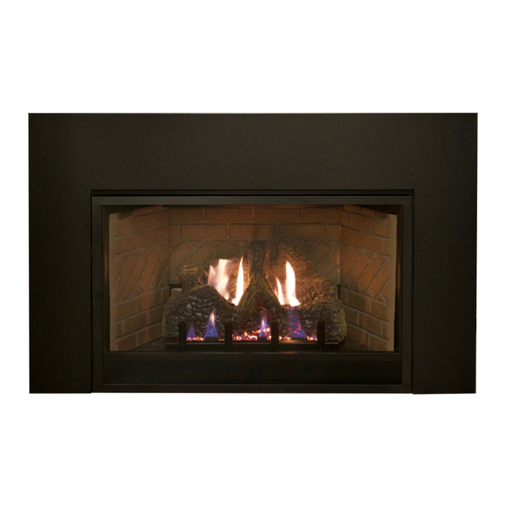
Vent - Free
Fireplace
Insert
Shown
Without
Required
Surround.
VFPC20IN33N - 1
VFPC20IN33P - 1
VFPC20IN73N - 2
VFPC20IN73P - 2
This is an unvented gas-fired heater. It uses air
(oxygen) from the room in which it is installed.
Provisions for adequate combustion and
ventilation air must be provided. Refer to pages
16 and 17.
WATER VAPOR: A BY-PRODUCT OF
UNVENTED ROOM HEATERS
Water vapor is a by-product of gas combustion.
An unvented room heater produces approximately
one (1) ounce (30ml) of water for every 1,000 BTU's
(.3KW's) of gas input per hour. Refer to page 16.
This appliance may be installed in an aftermarket,
permanently located, manufactured (mobile)
home, where not prohibited by local codes.
This appliance is only for use with the type of
gas indicated on the rating plate. This appliance
is not convertible for use with other gases.
VFPC28IN33N - 1
VFPC28IN33P - 1
VFPC28IN73N - 2
VFPC28IN73P - 2
Page 1
Advertisement
Table of Contents
Troubleshooting

Related Manuals for Empire Comfort Systems VFPC20IN73N-2


Summary of Contents for Empire Comfort Systems VFPC20IN73N-2
- Page 1 INSTALLATION INSTRUCTIONS AND OWNER'S MANUAL INSTALLER: UNVENTED GAS FIREPLACE MODELS: Leave this manual with the appliance. CONSUMER: Retain this manual for future reference. Vent - Free Fireplace Insert WARNING Shown FIRE OR EXPLOSION HAZARD Without Failure to follow safety warnings exactly Required could result in serious injury, death or Surround.
-
Page 2: Table Of Contents
TABLE OF CONTENTS SECTION PAGE Carton Contents And Hardware Pack .......................... 3 Before You Start ................................4 Important Safety Information ............................. 5-6 Safety Information For Users Of Propane Gas ......................6-7 Important Installation Guidelines ..........................7 Introduction .................................. 8 Specifications ................................9 Installation In A Fireplace ............................ -
Page 3: Carton Contents And Hardware Pack
CARTON CONTENTS & HARDWARE PACK QUANTITY SUPPLIED INDEX DESCRIPTION LOCATION NUMBER Fireplace Insert In carton Barrier Screen Assembly Front of Insert Warning Label Plate In envelope Flex Line with Shut-off Attached to the gas valve AA Batteries In envelope Wire Retainer Clips In envelope ON/OFF Switch In envelope... -
Page 4: Before You Start
BEFORE YOU START Unpacking the fireplace insert: WARNING Cut binding straps. Remove the top carton. Read and follow these safety precautions prior to operat- Carefully remove the carton contents. ing this appliance. Failure to follow these precautions may Use the Carton Contents and Hardware Pack lists on page 3 result in death, injury, or property damage. -
Page 5: Important Safety Information
IMPORTANT SAFETY INFORMATION DANGER: Indicates a hazardous situation which, if not avoided, will • WARNING: DO NOT operate this appliance unless all result in death or serious injury. components including logs, burners, and controls are in good working condition. Never operate this appliance if any log or twig WARNING: Indicates a hazardous situation which, if not avoided, is broken, or out of their intended position. -
Page 6: Safety Information For Users Of Propane Gas
– before the heating season. that Empire Comfort Systems accepts no responsibility for If you have pets or excessive dust, more frequent cleaning may this decision and any injury or damage due to this application be necessary. -
Page 7: Important Installation Guidelines
SAFETY INFORMATION FOR USERS OF PROPANE GAS (CONT'D) • If, at any time, you do not smell the Propane Gas odorant and If the valve is left open, then treat the container as a new tank. you think you should, assume you have a leak. Then take the Always be sure your container is under vapor pressure by same immediate action recommended above for the occasion turning it off at the container before it goes completely empty... -
Page 8: Introduction
INTRODUCTION Instructions to Installer Installation on Rugs and Tile Installer must leave instruction manual with owner after If this appliance is installed directly on carpeting, tile or other installation. combustible material other than wood flooring the appliance shall Installer must have owner fill out and mail warranty card supplied be installed on a metal or wood panel extending the full width and with unvented room heater. -
Page 9: Specifications
SPECIFICATIONS VFPC28IN3* Propane Natural Adaptor Kit Description Input Btu/hr Maximum 28,000 28,000 Surround Adaptor Kit - Required For Cast SAN20 Iron Surround With VFPC20IN Inserts Input Btu/hr Minimum 23,000 20,000 Surround Adaptor Kit - Required For Cast Orifice SAN28 Iron Surround With VFPC28IN Inserts Air Shutter Opening Full Open 1/8"... -
Page 10: Installation In A Fireplace
INSTALLATION IN A FIREPLACE First check to make sure there is no hidden damage to the NOTICE: If desired, it is acceptable to attach metal strapping unit. Take a minute and plan out the gas and electrical route. It or brackets (not provided) from the fireplace cavity to the insert is best to start with the gas line first, followed by the electrical outer jacket to secure the fireplace insert to the fireplace hearth supply requirements. -
Page 11: Fireplace Insert Dimensions
FIREPLACE INSERT DIMENSIONS VF FIREPLACE INSERT DIMENSIONS MODEL VFPC(10,20)IN 29-1/4" 19-1/8" 14-5/8" 25-7/8" 16-3/16" 13-9/16" 27-13/16" 18-1/8" 15/16" 13-9/16" 11/16" VFPC28IN 32-1/4" 22-1/8" 17-5/8" 28-7/8" 17-13/16" 15-1/16" 30-13/16" 21-1/8" 15/16" 14-15/16" 11/16" Figure 1 Fireplace Opening Dimensional Information/Sizing MINIMUM FIREPLACE OPENING DIMENSIONS FRONT REAR HEIGHT... -
Page 12: Built-In Fireplace Installation
BUILT-IN FIREPLACE INSTALLATION In planning the installation for the fireplace, it is necessary to The fireplace can be mounted on any of these surfaces: determine where the unit is to be installed and whether optional 1. A flat hard combustible or non-combustible surface. accessories are desired. -
Page 13: Vfpc20In Fireplace Surround Dimensions
VFPC20IN FIREPLACE SURROUND DIMENSIONS 1” 21 - 1/2" 21 1/2” 34" 34” DS20433BL 1” 21 - 1/2" 24 1/2” 40" 40” DS20763BL 43165-1-1221 Page 13... -
Page 14: Vfpc28In Fireplace Surround Dimensions
VFPC28IN FIREPLACE SURROUND DIMENSIONS 1" 1” 21 - 1/2" 24 1/2” 37" 37” DS28433BL 1" 1” 21 - 1/2" 27 1/2” 43" 43” DS28763BL Page 14 43165-1-1221... -
Page 15: Alternate On/Off Switch Installation (With Cast Iron Surround)
ALTERNATE ON/OFF SWITCH INSTALLATION Cast Iron Surrounds Cast Iron Surrounds require a surround adaptor kit. See page 9 for kit information. Find the coiled low voltage wire assembly and ON/OFF switch located in the instruction packet. 2a. Attach the flag terminal ends to the “TH/TP”... -
Page 16: Water Vapor: A By-Product Of Unvented Room Heaters
WATER VAPOR: A BY-PRODUCT OF UNVENTED ROOM HEATERS Water vapor is a by-product of gas combustion. An unvented room The following steps will help insure that water vapor does not heater produces approximately one ounce (30ml) of water for every become a problem. - Page 17 PROVISIONS FOR ADEQUATE COMBUSTION & VENTILATION AIR (CONT'D) The space in the above example is a confined space because the Ventilation Air From Outdoors actual BTU/Hr used is more than the maximum BTU/HR the space Provide extra fresh air by using ventilation grills or ducts. You must can support.
-
Page 18: Gas Supply
GAS SUPPLY The gas pipeline can be brought in through the right or left side of Installing the Main Gas Shut-Off the appliance. The insert has a Flexline with shutoff valve located on Each appliance should have its own manual gas shut-off. the right side when facing the unit. -
Page 19: (Combustible) Clearances
GAS SUPPLY (CONT'D) Checking Manifold Pressure Propane Gas will have a manifold pressure approximately 10.0"w.c. MILLIVOLT VALVES at the pressure regulator outlet with the inlet pressure to the pressure Natural Gas will have a manifold pressure of approximately 3.5" w.c. regulator from a minimum of 11.0"w.c. -
Page 20: Combustible Materials
COMBUSTIBLE MATERIALS Combustible Material No greeting cards, stockings or ornamentation of any type should be No greeting cards, stockings or ornamentation of any type should placed on or attached to the fireplace. This is a heating appliance. be placed on or attached to the fireplace. The flow of heat can The flow of heat can ignite combustibles. -
Page 21: Millivolt Alternate On/Off Switch Installation (Standard Surrounds)
MILLIVOLT ALTERNATE ON/OFF SWITCH INSTALLATION (STANDARD SURROUNDS) WIRING THE FIREPLACE Connect the low voltage wires from the gas valve to the ON/OFF switch. CAUTION a. For millivolt valve connections, See Figure 19. b. For IP valve connections, locate the green and white wires Disconnect remote controls if you are absent for extended from the control module, then connect the switch wire flag time periods. -
Page 22: Blower Accessory Information
BLOWER ACCESSORY INFORMATION The appliance, when installed must be electrically THE FAN CONTROL SWITCH IS CLIPPED BETWEEN THE BURNER connected and grounded in accordance with local codes BASE AND VALVE BRACKET BLOWER ASSEMBLY or, in the absence of local codes, with the current CSA C22.1 Canadian Electrical Code. -
Page 23: Vfpc20In Log Placement
Page 25. Replacement of loose material (glowing embers) must be The following WARNING applies when log set is installed onto an purchased from Empire Comfort Systems, Inc. Application of excess unvented gas burner assembly. loose material (glowing embers) may adversely affect performance of the heater. -
Page 24: Vfpc20In Ember Placement Photo
VFPC20IN EMBER PLACEMENT PHOTO Do not cover any large rear ports with Do not cover any large rear ports with loose material (glowing embers). loose material (glowing embers). Do not cover any large rear ports with loose material (glowing embers). Page 24 43165-1-1221... -
Page 25: Vfpc28In Log Placement
Figure 25 Page 26. Replacement of loose material (glowing embers) must be purchased from Empire Comfort Systems, Inc. Application of excess The following WARNING applies when log set is installed onto an loose material (glowing embers) may adversely affect performance unvented gas burner assembly. -
Page 26: Vfpc28In Ember Placement Photo
VFPC28IN EMBER PLACEMENT PHOTO Do not cover any large rear ports with Do not cover any large rear ports with loose material (glowing embers). loose material (glowing embers) Photo 2 Do not cover any large front ports with Do not cover any large front ports with loose material (glowing embers). -
Page 27: Millivolt Control Valve Lighting Instructions
MILLIVOLT CONTROL VALVE LIGHTING INSTRUCTIONS FOR YOUR SAFETY READ BEFORE LIGHTING WARNING If you do not follow these instructions exactly, a fire or explosion may result causing property damage, personal injury or loss of life. A. This appliance has a pilot which must be lit by hand. When C. -
Page 28: Operation Instructions/Flame Appearance
OPERATION INSTRUCTIONS/FLAME APPEARANCE Flames from the pilot (rear right back side of the pan burner) as PERIODIC CLEANING – Refer to parts diagram for location of well as the main flame should be visually checked as the log set items discussed below. is installed. -
Page 29: Millivolt Pilot Flame Characteristics
MILLIVOLT PILOT FLAME CHARACTERISTICS Figures 26 and 28 show a correct pilot flame pattern. The correct flame will be blue and will extend beyond the thermocouple. The flame will surround the thermocouple just below the tip. A slight yellow flame may occur where the pilot flame and main burner flame meet. -
Page 30: Pilot Flame Characteristics
PILOT FLAME CHARACTERISTICS INTERMITTANT PILOT CLEANING AND PILOT MAINTENANCE Oxygen Depletion Sensor Pilot - Figures 30 and 31 IGNITOR When the pilot has a large yellow tip flame, clean the Oxygen Depletion Sensor as follows: SENSOR Clean the ODS pilot by loosening nut B from the pilot tubing. When this procedure is required, grasp nut A with an open end wrench. -
Page 31: Wiring
WIRING Label all wires prior to disconnection when servicing controls. Wiring Remote Receiver errors can cause improper and dangerous operation. Verify proper Use the following steps to place optional remote receiver adjacent operation after servicing. to the gas valve. Millivolt thermopile is self powered, gas valve does not require 110 The remote receiver can not be placed behind the gas valve volts. -
Page 32: Troubleshooting Symptoms - Possible Causes And Corrections
TROUBLESHOOTING SYMPTOMS - POSSIBLE CAUSES AND CORRECTIONS Turn appliance OFF and allow to cool before servicing. Only a qualified service person should service and repair the heater. Pilot flame not touching thermocouple, which allows When ignitor button is pressed, there is no spark at ODS/ thermocouple to cool, causing pilot flame to go out. -
Page 33: Intermittent Pilot Lighting Instructions
INTERMITTENT PILOT LIGHTING INSTRUCTIONS FOR YOUR SAFETY READ BEFORE LIGHTING WARNING If you do not follow these instructions exactly, a fire or explosion may result causing property damage, personal injury or loss of life. A. This appliance has a pilot which must be lighted by hand. When C. -
Page 34: Ipi Electronic System Operating Instructions
IPI ELECTRONIC SYSTEM OPERATING INSTRUCTIONS 5.25 VDC ELECTRONIC CONTROL VALVE Follow the SAFETY and LIGHTING INSTRUCTIONS for In- The electronic control valve system includes the ability to switch termittent Pilot controls found in this manual, and on labels the pilot from a standing pilot mode to an intermittent pilot mode. found in the control compartment located in the lower cavity •... -
Page 35: Ipi Electronic System Wiring Diagram
IPI ELECTRONIC SYSTEM WIRING DIAGRAM BLUE BLUE GREEN WHITE WHITE ORANGE CPI/IPI SWITCH ON/OFF REMOTE RECEIVER PILOT SWITCH (OPTIONAL) YELLOW + ON REMOTE - OFF BLACK BLACK GAS CONTROL VALVE (GND) WHITE GREEN BLACK AC/DC POWER ADAPTOR BLACK ELECTRONIC CONTROL MODULE BATTERY HOLDER Figure 34 If any of the original wire as supplied with this unit must be replaced, it must be replaced with equivalent gauge and temperature... - Page 36 This page intentionally left blank. Page 36 43165-1-1221...
-
Page 37: Intermittent Control System Troubleshooting
Brief Description of the Components The gas valve is equipped with a manual HI/LO knob to allow for manual modulation of the gas outlet pressure. The manual HI/LO knob can be replaced by an Empire Comfort Systems Variable Remote Kit. WARNING This appliance is equipped for (Natural or Propane Gas). - Page 38 INTERMITTENT CONTROL SYSTEM TROUBLESHOOTING PROBLEM OBSERVED POSSIBLE CAUSE CORRECTIVE MEASURE What To Do If You Smell Gas • Do not try to light any appliance. Gas odor during setup • Do not touch any electrical switch; • Do not use any phone in your building. Gas Leak •...
- Page 39 INTERMITTENT CONTROL SYSTEM TROUBLESHOOTING PROBLEM OBSERVED POSSIBLE CAUSE CORRECTIVE MEASURE Low gas pressure Check gas supply pressure Loose sensor wire Check wire connection Valve not grounded well Check ground connections Clogged or dirty burner ports Clean burner ports (For fireplace equipped with optional Move (optional) remote away from fireplace Burner lights but does not stay lit thermostat or thermostat remote) Room...
- Page 40 INTERMITTENT CONTROL SYSTEM TROUBLESHOOTING If the DFC giving signal lock out: Verify the electrical connections’ integrity and The board should be unlocked to make sure they are in accordance with the relevant reinitiate a pilot flame ignition (for Is the DFC board in system wiring diagram.
- Page 41 INTERMITTENT CONTROL SYSTEM TROUBLESHOOTING Replace DFC board. Main burner lights when the pilot only Replace the gas valve. should light. Verify the pilot flame fully engulfs the tip of the sense electrode. If not replace the pilot assembly. Replace the pilot assembly. Carefully clean the electrical connections of the sense cable, and the DFC board sense cable connection.
-
Page 42: Vfpc(20,28)In Parts List
VFPC(20,28)IN PARTS LIST MODELS INDEX DESCRIPTION NUMBER VFPC20IN33 VFPC28IN33 VFPC20IN73 VFPC28IN73 INSERT PAINTED ASSY 39769 39770 39769 39770 BAFFLE, FLUE 21642 21642 21642 21642 BRICK LINER BRACKET R9192 R9196 R9192 R9196 BRICK PANEL, BACK R9195 R9198 R9195 R9198 BRICK PANEL, RIGHT SIDE R9194 R9197 R9194... - Page 43 VFPC(20,28)IN PARTS LIST MODELS INDEX DESCRIPTION NUMBER VFPC20IN33 VFPC28IN33 VFPC20IN73 VFPC28IN73 33809 26169 TUBING ASSY, REGULATOR TO PILOT (NATURAL) R7063 R7063 PILOT REGULATOR (NATURAL) 29816 26171 TUBING ASSY, REGULATOR TO VALVE (NATURAL) 26167 26167 TUBING ASSEMBLY - PILOT (PROPANE) 33809 29820 TUBING ASSY, PILOT TO REGULATOR (NATURAL) R7063...
-
Page 44: Vfpc(20,28)In Parts View
VFPC(20,28)IN PARTS VIEW MILLIVOLT VALVE ASSEMBLY INTERMITTENT PILOT (IP) VALVE ASSEMBLY Page 44 43165-1-1221... -
Page 45: Log Parts Lists And Parts Views
LOGS PARTS LISTS & PARTS VIEWS ATTENTION: When ordering parts, it is very important that part number and description of part coincide. Index Part DESCRIPTION VFPC20IN LOG SET R7504 LEFT FRONT LOG R7505 RIGHT FRONT LOG R7506 BACK LOG USE ONLY MANUFACTURER'S REPLACEMENT PARTS. USE OF ANY OTHER PARTS COULD CAUSE INJURY OR DEATH. ATTENTION: When ordering parts, it is very important that part number and description of part coincide. -
Page 46: Master Parts Distributor List
This list changes from time to time. For the current list, please click on the Master Parts button at www.empirecomfort.com. Please note: Master Parts Distributors are independent businesses that stock the most commonly ordered Original Equipment repair parts for Heaters, Grills, and Fireplaces manufactured by Empire Comfort Systems Inc. Dey Distributing F. -
Page 47: Warranty
WARRANTY Empire Comfort Systems Inc. warranties this hearth product to be free from defects at the time of purchase and for the periods specified below. This warranty applies to the original purchaser only and is not transferable. All warranty repairs must be accomplished by a qualified gas appliance technician. - Page 48 Empire Comfort Systems Inc. Belleville, IL If you have a general question about our products, please e-mail us at info@empirecomfort.com. If you have a service or repair question, please contact your dealer. www.empirecomfort.com Page 48 43165-1-1221...
Need help?
Do you have a question about the VFPC20IN73N-2 and is the answer not in the manual?
Questions and answers