Table of Contents
Advertisement
Quick Links
The Vail Vent-Free Gas Fireplaces
INSTALLER:
Leave this manual with the appliance.
CONSUMER:
Retain this manual for future reference.
WARNING
FIRE OR EXPLOSION HAZARD
Failure to follow safety warnings exactly
could result in serious injury, death or
property damage.
— Do not store or use gasoline or other
flammable vapors and liquids in the
vicinity of this or any other appliance.
— WHAT TO DO IF YOU SMELL GAS
•
Do not try to light any appliance.
•
Do not touch any electrical switch;
do not use any phone in your building.
•
Leave the building immediately.
•
Immediately call your gas supplier
from a neighbor's phone. Follow
the gas supplier's instructions.
•
If you cannot reach your gas
supplier, call the fire department.
— Installation and service must be
performed by a qualified installer,
service agency or the gas supplier.
INSTALLATION INSTRUCTIONS
AND OWNER'S MANUAL
UNVENTED GAS FIREPLACE
HYDRAULIC THERMOSTAT
MODELS:
VFP24FP2(0,1,2,3)L(N,P)-1
MILLIVOLT MODELS:
VFP24FP3(0,1,2,3)L(N,P)-1
VFP24FP3(0,1,2,3)L10(N,P)-1 (10,000 BTU UNIT)
INTERMITTENT PILOT MODELS:
VFP24FP7(0,1,2,3)L(N,P)-1
VFP24FP7(0,1,2,3)L10(N,P)-1 (10,000 BTU UNIT)
WARNING
If not installed, operated and maintained
in accordance with the manufacturer's
instructions, this product could expose you
to substances in fuel or from fuel combustion
which can cause death or serious illness.
This is an unvented gas-fired heater. It uses
air (oxygen) from the room in which it is
installed. Provisions for adequate combustion
and ventilation air must be provided. Refer
to page 7.
WATER VAPOR: A BY-PRODUCT OF UNVENTED
ROOM HEATERS
Water vapor is a by-product of gas combustion.
An unvented room heater produces
approximately one (1) ounce (30ml) of water
for every 1,000 BTU's (.3KW's) of gas input
per hour. Refer to pages 7 and 8.
Page 1
Advertisement
Table of Contents
Troubleshooting

Related Manuals for Empire Comfort Systems VFP24FP30


Summary of Contents for Empire Comfort Systems VFP24FP30
- Page 1 INSTALLATION INSTRUCTIONS AND OWNER’S MANUAL The Vail Vent-Free Gas Fireplaces UNVENTED GAS FIREPLACE HYDRAULIC THERMOSTAT MODELS: VFP24FP2(0,1,2,3)L(N,P)-1 MILLIVOLT MODELS: VFP24FP3(0,1,2,3)L(N,P)-1 VFP24FP3(0,1,2,3)L10(N,P)-1 (10,000 BTU UNIT) INTERMITTENT PILOT MODELS: VFP24FP7(0,1,2,3)L(N,P)-1 VFP24FP7(0,1,2,3)L10(N,P)-1 (10,000 BTU UNIT) WARNING If not installed, operated and maintained INSTALLER: in accordance with the manufacturer's Leave this manual with the appliance.
-
Page 2: Table Of Contents
TABLE OF CONTENTS SECTION PAGE IMPORTANT SOOT PREVENTION STEPS ........................ 3 PRODUCT SPECIFICATIONS ............................. 4 FIREPLACE DIMENSIONS ............................5 CLEARANCES ................................6 COMBUSTIBLE MATERIAL ............................6 SPECIFICATIONS ................................ 7 WATER VAPOR: A BY-PRODUCT OF UNVENTED ROOM HEATERS ..............7 PROVISIONS FOR ADEQUATE COMBUSTION & VENTILATION AIR ..............7-8 INTRODUCTION ................................ -
Page 3: Important Soot Prevention Steps
IMPORTANT SOOT PREVENTION STEPS NOTICE IMPORTANT NOTICE INSTALLER - SERVICE PERSON - HOMEOWNER SOOT MAY BE CREATED IF THE FOLLOWING DIRECTIONS ARE NOT FOLLOWED. Ensure the air shutter is set to the specification. See Figures Verify the air shutter for the correct setting. Refer to the tables for 1 and 3 and the table on page 4. -
Page 4: Product Specifications
PRODUCT SPECIFICATIONS NATURAL GAS PROPANE GAS Hydraulic Millivolt Hydraulic Millivolt Regulator Pressure Setting 10.0 10.0 10.0 Gas Inlet Pressure - Maximum 10.5 10.5 10.5 13.0 13.0 13.0 Gas Inlet Pressure - Minimum 11.0 11.0 11.0 MODEL VALVE TYPE ORIFICE BTUH MAX. RATE BTUH MIN. -
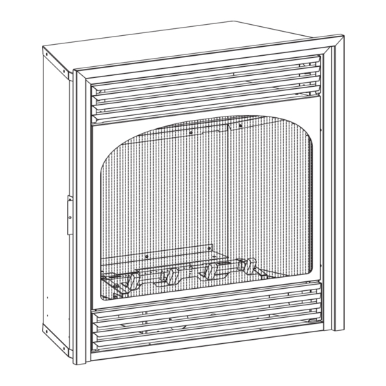
Page 5: Fireplace Dimensions
FIREPLACE DIMENSIONS VFP24 INDEX LETTER DIMENSION DESCRIPTION Dimensions in Inches The maximum height of firebox face (excluding standoffs) 26-1/2 The maximum width of the firebox face (excluding nailing flanges) The maximum depth of the firebox The height of the firebox opening 17-1/2 The width of the firebox opening 19-1/2... -
Page 6: Clearances
CLEARANCES Minimum Wall and Ceiling Clearances Mantel Clearances for Built-in Installation Mantel 12” (305mm) 34 3/16” 10” (843mm) (254mm) 15 3/16” 8” (386mm) (203mm) 14 7/16” 6” (367mm) (152mm) 13 11/16” (348mm) 4” 12 15/16” (102mm) (329mm) 2 1/2” (63mm) 9 11/16”... -
Page 7: Specifications
SPECIFICATIONS ACCESSORIES VFP24FP3*L VFP24FP2*L VFP24FP3*L10 VFP24FP7*L10 VFP24FP7*L MODEL FBB6 Automatic Blower Natural Propane Natural Propane Natural Propane Natural Propane VPP1A-22 Aged Brick Liner Input 20,000 20,000 10,000 10,000 VFF24HP-1 Hammered Pewter Trim Kit Max. ACCESSORIES FOR MILLIVOLT AND Input 14,000 10,000 10,000 10,000... - Page 8 PROVISIONS FOR ADEQUATE COMBUSTION & VENTILATION AIR 3. Add the BTU/Hr of all fuel burning appliances in the space. Vent-free heater BTU/Hr Gas water heater BTU/Hr Gas furnace BTU/Hr Vented gas heater BTU/Hr Gas fireplace logs BTU/Hr Other gas appliances* + BTU/Hr Total BTU/Hr...
-
Page 9: Introduction
INTRODUCTION Instructions to Installer Any alteration of the original design, installed other than as 1. Installer must leave instruction manual with owner after shown in these instructions or use with a type of gas not installation. shown on the rating plate is the responsibility of the person and company making the change. -
Page 10: Gas Supply
GAS SUPPLY Pressure Testing of the Gas Supply System Check all local codes for requirements, especially for the size and type of gas supply line required. To check the inlet pressure to the gas valve, a 1/8" (3mm) N.P.T. plugged tapping, accessible for test gauge connection, must RECOMMENDED GAS PIPE DIAMETER be placed immediately upstream of the gas supply connection Schedule 40 Pipe... -
Page 11: Installation Of Fireplace Into Mantel
INSTALLATION OF FIREPLACE INTO MANTEL Position base approximately 5" from wall surface. Installing Fireplace in Mantel Attach nailing flange to fireplace top with two 10 x 1/2" screws. Place fireplace on top of base. Gas line connections must be made at this time. When facing the fireplace the gas supply will enter on right-hand side. -
Page 12: Built-In Fireplace Installation
BUILT-IN FIREPLACE INSTALLATION Built-In Fireplace Installation Rough Opening for Installing in Corner Built-in installation of this fireplace involves installing fireplace into a framed-in enclosure. This makes the front of fireplace flush with wall. If installing a mantel above the fireplace, you must follow the clearances shown in Figure 5, page 9. -
Page 13: Vfp24 Log Identification
VFP24 LOG IDENTIFICATION Part Front View Top View Description Number Log A R7506 Log B R7504 Log C R7505 30411-16-0919 Page 13... -
Page 14: Log Placement
LOG PLACEMENT Before you begin: Do not, handle these logs with your bare hands! NOTICE: Replacement Glowing Embers must be purchased from Always wear gloves to prevent skin irritation. After handling logs, an authorized distributor. wash your hands gently with soap and water. Attention: When ordering parts, it is very important that part num- ALL LOGS ber and description of part coincide. - Page 15 LOG PLACEMENT 1. Place Log A between rear log support and burner pan. See image below 30411-16-0919 Page 15...
- Page 16 LOG PLACEMENT 2. Place Log B onto the two left, front pins on the burner pan. Page 16 30411-16-0919...
- Page 17 LOG PLACEMENT 3. Place Log C onto the two right, front pins on burner pan. See image below. 30411-16-0919 Page 17...
- Page 18 LOG PLACEMENT 4. Log set assembly is complete. Page 18 30411-16-0919...
-
Page 19: Placement Of Glowing Embers (Rock Wool)
Replacement of loose material (glowing embers) must be purchased wool) to be placed between logs on the flat metal surface of the from Empire Comfort Systems, Inc. Application of excess loose burner. material (glowing embers) may adversely affect performance of the heater. -
Page 20: Pilot Flame Characteristics
PILOT FLAME CHARACTERISTICS Figures 13, 14 and 15 show a correct pilot flame pattern. The meet. Figures 16, 17 and 18 show an incorrect pilot flame pattern. correct flame will be blue and will extend beyond the thermocouple. The incorrect pilot flame is not touching the thermocouple. This will The flame will surround the thermocouple just below the tip. -
Page 21: Hydraulic Thermostat Models Lighting Instructions
HYDRAULIC THERMOSTAT MODELS LIGHTING INSTRUCTIONS FOR YOUR SAFETY READ BEFORE LIGHTING WARNING If you do not follow these instructions exactly, a fire or explosion may result causing property damage, personal injury or loss of life. A. This appliance has a pilot which must be lighted by hand. C. -
Page 22: 10,000 Btu Millivolt Control Valve Lighting Instructions
10,000 BTU MILLIVOLT CONTROL VALVE LIGHTING INSTRUCTIONS FOR YOUR SAFETY READ BEFORE LIGHTING WARNING If you do not follow these instructions exactly, a fire or explosion may result causing property damage, personal injury or loss of life. A. This appliance has a pilot which must be lighted by hand. C. -
Page 23: Millivolt Control Lighting Instructions
MILLIVOLT CONTROL LIGHTING INSTRUCTIONS FOR YOUR SAFETY READ BEFORE LIGHTING WARNING If you do not follow these instructions exactly, a fire or explosion may result causing property damage, personal injury or loss of life. A. This appliance has a pilot which must be lighted by hand. C. -
Page 24: Millivolt Wiring
MILLIVOLT WIRING Label all wires prior to disconnection when servicing controls. Wiring Remote Receiver errors can cause improper and dangerous operation. Verify proper Use the following steps to place the remote receiver adjacent to operation after servicing. the gas valve. Attention: The remote receiver bracket is not used in this Millivolt thermopile is self powered, gas valve does not require 110 installation. -
Page 25: Millivolt Troubleshooting Symptoms, Possible Causes And Corrections
MILLIVOLT TROUBLESHOOTING SYMPTOMS, POSSIBLE CAUSES AND CORRECTIONS Turn appliance OFF and allow to cool before servicing. Only a qualified service person should service and repair the heater. When ignitor button is pressed, there is no spark at ODS/ pilot lights, keep control knob pressed in 30 seconds. pilot. -
Page 26: Intermittent Pilot Lighting Instructions
INTERMITTENT PILOT LIGHTING INSTRUCTIONS FOR YOUR SAFETY READ BEFORE LIGHTING WARNING If you do not follow these instructions exactly, a fire or explosion may result causing property damage, personal injury or loss of life. A. This appliance has a pilot which must be lighted by hand. When C. -
Page 27: Intermittent Control System Operating Instructions
INTERMITTENT CONTROL SYSTEM OPERATING INSTRUCTIONS 5.25 VDC ELECTRONIC CONTROL VALVE Follow the SAFETY and LIGHTING INSTRUCTIONS for In- termittent Pilot controls found in this manual, and on labels The electronic control valve system includes the ability to switch found in the control compartment located in the lower cavity the pilot from a standing pilot mode to an intermittent pilot mode. -
Page 28: Intermittent Control System Wiring Diagram
INTERMITTENT CONTROL SYSTEM WIRING DIAGRAM If any of the original wire as supplied with this unit must be replaced, it must be replaced with equivalent gauge and temperature rated wire. This appliance is only for use with the type of gas indicated on the rating plate and may be installed in an aftermarket, permanently located, manufactured (mobile) home where not prohibited by local codes. -
Page 29: Intermittent Control System Troubleshooting
Brief Description of the Components The gas valve is equipped with a manual HI/LO knob to allow for manual modulation of the gas outlet pressure. The manual HI/LO knob can be replaced by an Empire Comfort Systems Variable Remote Kit. WARNING This appliance is equipped for Natural or Propane Gas. -
Page 30: Troubleshooting
TROUBLESHOOTING PROBLEM OBSERVED POSSIBLE CAUSE CORRECTIVE MEASURE What To Do If You Smell Gas Gas odor during setup Gas Leak Do not try to light any appliance. Do not touch any electrical switch; Do not use any phone in your building. Immediately call your gas supplier from a Gas odor before first ignition Gas Leak... - Page 31 TROUBLESHOOTING PROBLEM OBSERVED POSSIBLE CAUSE CORRECTIVE MEASURE Flame sensor dirty Clean pilot sensor Low gas pressure Check gas supply pressure Not enough fresh air for pilot Open door or window - ventilate Clogged or dirty burner ports Clean burner ports (For fireplace equipped with optional Move (optional) remote away from fireplace Burner &...
-
Page 32: Parts List
PARTS LIST ATTENTION: When ordering parts, it is very important that part number and description of part coincide. INDEX PART INDEX PART DESCRIPTION DESCRIPTION NUMBER NUMBER NUMBER NUMBER COMMON VFP24FP30L and VFP24FP30L10 25897 TRIM - TOP R3623 PILOT ASSEMBLY - PROPANE 25895 TRIM - LEFT R3624... - Page 33 PARTS LIST ATTENTION: When ordering parts, it is very important that part number and description of part coincide. INDEX PART INDEX PART DESCRIPTION DESCRIPTION NUMBER NUMBER NUMBER NUMBER VFP24FP70L VFP24FP70L10 R11328 PILOT ASSEMBLY, NATURAL R11328 PILOT ASSEMBLY, NATURAL R11327 PILOT ASSEMBLY, PROPANE R11327 PILOT ASSEMBLY, PROPANE R5676...
-
Page 34: Parts View
PARTS VIEW VFP24FP7 Series VFP24FP2 Series VFP24FP3 Series 34 33 Page 34 30411-16-0919... -
Page 35: Maintenance And Service
MAINTENANCE AND SERVICE PERIODIC CLEANING – Refer to parts diagram for location of items discussed below. • Do not use cleaning fluid to clean logs or any part of heater. • Logs - brush with soft bristle brush or vacuum with brush attachment. -
Page 36: Important Safety Information
IMPORTANT SAFETY INFORMATION THIS IS A HEATING APPLIANCE DANGER: Indicates a hazardous situation which, if not avoided, will • WARNING! This fireplace needs fresh air for ventilation to run properly. This fireplace has an ODS (oxygen depletion result in death or serious injury. sensor) which will shut down the heater if adequate fresh air is WARNING: Indicates a hazardous situation which, if not avoided, not available. -
Page 37: Safety Information For Users Of Propane Gas
SAFETY INFORMATION FOR USERS OF PROPANE GAS Propane is a flammable gas which can cause fires and explo- SOME POINTS TO REMEMBER sions. In its natural state, propane is odorless and colorless. • Learn to recognize the odor of Propane Gas. Your local Propane You may not know all the following safety precautions which Gas Dealer can give you a “Scratch and Sniff”... -
Page 38: Master Parts Distributor List
This list changes from time to time. For the current list, please click on the Master Parts button at www.empirecomfort.com. Please note: Master Parts Distributors are independent businesses that stock the most commonly ordered Original Equipment repair parts for Heaters, Grills, and Fireplaces manufactured by Empire Comfort Systems Inc. Dey Distributing F. -
Page 39: Warranty
WARRANTY Empire Comfort Systems Inc. warranties this hearth product to be free from defects at the time of purchase and for the periods specified below. Hearth products must be installed by a qualified technician and must be maintained and operated safely, in accordance with the instructions in the owner’s manual. - Page 40 Empire Comfort Systems Inc. Belleville, Illinois If you have a general question about our products, please e-mail us at info@empirecomfort.com. If you have a service or repair question, please contact your dealer. www.empirecomfort.com Page 40 30411-16-0919...
Need help?
Do you have a question about the VFP24FP30 and is the answer not in the manual?
Questions and answers