
Related Manuals for CO-Z SL1000AC


Summary of Contents for CO-Z SL1000AC
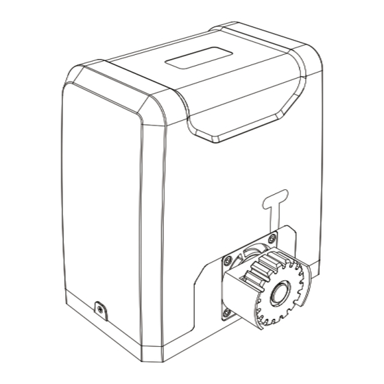
- Page 1 V20230201 SL1000AC/SL1500AC SLIDING GATE OPENER USER MANUAL Read Carefully Before Use Keep for Future Reference...
-
Page 2: Safety Information
SAFETY INFORMATION Warning! • Read these instructions CAREFULLY before installation and use. Provide them to any technician used to install, maintain, or repair this device and provide them with the device if it is ever given or sold to a third party. Install and use this gate opener ONLY in accordance with these instructions and all applicable local and •... -
Page 3: Specifications
SPECIFICATIONS Model SL1000AC SL1500AC Input Power 110–120 V~ 60 Hz 110–120 V~ 60 Hz Rated Power 0.54 hp 400 W 0.73 hp 550 W Torque 16.2 lb.-ft. 22 N·m 23.6 lb.-ft. 32 N·m Duty Cycle S2 20 min. S2 20 min. - Page 4 Picture Name Quantity Module 4 Racks Limit Switches with Accessories M10 Foundation Bolts M6×18 Mounting Bolts M10×50 Hex Bolts Self-Tapping Screws Mounting Lugs M10 Flat Washers M10 Spring Washers M10 Nuts Infrared Sensor Set...
-
Page 5: Installation
INSTALLATION Initial Testing and Setup 1. When you first receive your motor (A), use one of the manual release keys (B) to open the motor’s release bar 90°. This releases the main gear’s normal locking mechanism for manual testing. Confirm that the gear rotates freely and smoothly by hand. - Page 6 Press the button again to stop the gear. Press the button a third time to start the motor again in reverse. This should cause the gear to begin turning clockwise, which closes gates from the right. Press the button a fourth time to stop it again.
-
Page 7: Base Installation
7. Provide a stable, compatible, and well-grounded power connection for the gate opener. The motor’s outlet should be within sight of the gate, protected from the elements, and equipped with a GFCI, RCD, or circuit breaker. It should be at least 3 feet (1 m) high to minimize damage from weather. If possible, place the outlet higher than 5 feet (1.5 m) to limit access by children and animals. - Page 8 The outer edge of the gear will need to be positioned almost exactly ¾″ (19 mm) from the nearest part of the gate. The mounting plate (D) can be used to more easily check and mark initial placement, but its outer edge will need to be positioned 2⅛″...
-
Page 9: Motor Installation
Motor Installation Using two people may make some parts of the following process much easier. 1. Remove the bolts on each side of the protective casing of the motor (A). Remove the rubber grommet near the limit switch sensor as shown and remove the casing from the motor. Use your release key (B) to unlock the gear again. - Page 10 7. Remove the protective cover from the motor circuit board. Keep its fasteners nearby. NEVER make electrical connections while the motor’s power supply is active. Disconnect the GFCI, RCD, or circuit breaker before any wiring attempt. 8. If you will need to directly wire your power source into the motor’s circuit board, connect your wires to the main power terminal, the only one with three pin positions.
-
Page 11: Rack Installation
Rack Installation 1. Before placing your racks, lay them out in position along the entire length of the gate where they will need to be installed. Check that both ends have at least one foot (30 cm) beyond the expected position of the main gear for their limit switch and ensure that you will not end up with a small piece of a rack at the end that is only supported by a single brace. -
Page 12: Limit Switch Installation
3. Unlock your main gear with your release key and move the gate back and forth. The gear should turn freely without binding along the entire length of the rack. The rack should remain in the same perfectly straight line over the gear from one end to the other, and there should be a space of about 40–80 mil (1–2 mm) between the gear and the rack along its entire length. -
Page 13: Circuit Board Diagram
ADJUSTMENT Circuit Board Diagram Adjustment Knobs DIP Switches Power Indicator Pairing Button Pairing Indicator J5 Terminal Alarm Switch Alarm J6 Terminal J2 Terminal 10A Fuse J4 Terminal J3 Terminal Adjustment Knobs DIP Switches Obstruction Sensitivity Deactivate Slow Start Braking Force Reverse Direction Slow Stop Distance Autoclose Time... -
Page 14: Reversing Direction
NEVER adjust any wiring or board setting while the gate is connected to power unless specifically directed otherwise. Disconnect the circuit from power, make your adjustment, and then restore power to test the effect. Reversing Direction The default placement for this system is on the right side of sliding gates DIP2 Effect when looking out from the property. -
Page 15: Remote Pairing
Adjusting the Gate’s Forcefulness Various settings control the forcefulness of the gate. The gate normally minimizes wear by speeding up gradually as it begins moving. DIP Switch 1 can be flipped up to deactivate this soft start. (This can damage the system and is not usually recommended.) Similarly, the rightmost adjustment knob VR4 controls the gate’s initial force. -
Page 16: Initial Testing
INITIAL TESTING 1. If the motor is located on the right side of your gate, confirm that DIP Switch 2 is toggled up. If the motor is located on the left side, make sure that DIP Switch 2 is toggled down. Power Remote Pairing 2. -
Page 17: Maintenance
MAINTENANCE • Always supervise children and pets near the gate, the motor, and their controls to prevent accidents. • Always fully disconnect your motor from its power supply before removing its cover or making any adjustments to its wiring. Use trained and licensed electricians for rewiring or electrical repair work. •... - Page 18 DISPOSAL Electrical products should not be disposed of with household products. In the EU and UK, according to the European Directive 2012/19/EU for the disposal of electrical and electronic equipment and its implementation in national laws, used electrical products must be collected separately and disposed of at the collection points provided for this purpose.
Need help?
Do you have a question about the SL1000AC and is the answer not in the manual?
Questions and answers
we need instrucion and help with the sl600acl
@sharon smith-wise
The CO-Z SL1000AC sliding gate opener must be installed and used according to the user manual and all applicable laws. Key instructions and help include:
- Read the manual carefully before installation and use.
- Provide the manual to any technician servicing the device.
- Use the opener only for a single sliding gate in Class I residential settings.
- Install it on firm, level ground, keeping hazardous components out of public areas.
- Ensure the gate is properly installed, plumb, level, and moves smoothly.
- Check that the track is clean, securely mounted, and flush.
- Include warning signs and block off hazardous areas if they cannot be eliminated.
- Ensure the gate can firmly mount the Module 4 rack and has end catches and stops.
- Inspect all components before use and replace only with identical parts.
These measures help ensure safe and proper operation.
This answer is automatically generated