Advertisement
Quick Links
O
PERATOR'S
IMPORTANT: READ SAFETY RULES AND INSTRUCTIONS CAREFULLY
Warning:
This unit is equipped with an internal combustion engine and should not be used on or near any unimproved forest-
covered, brush-covered or grass-covered land unless the engine's exhaust system is equipped with a spark arrester meeting
applicable local or state laws (if any). If a spark arrester is used, it should be maintained in effective working order by the operator.
In the State of California the above is required by law (Section 4442 of the California Public Resources Code). Other states may have
similar laws. Federal laws apply on federal lands. A spark arrester for the muffler is available through your nearest engine authorized
service dealer or contact the service department, P.O. Box 368022 Cleveland, Ohio 44136-9722.
MTD PRODUCTS INC. P.O. BOX 368022 CLEVELAND, OHIO 44136-9722
PRINTED IN U.S.A.
M
ANUAL
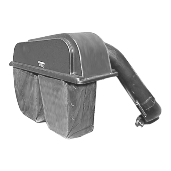
Twin Bag Grass
Collector
OEM-190-063
OEM-190-103
FORM NO. 770-10253B
Models
(9/99)
Advertisement

Subscribe to Our Youtube Channel
Related Manuals for MTD OEM-190-063


Summary of Contents for MTD OEM-190-063
- Page 1 Federal laws apply on federal lands. A spark arrester for the muffler is available through your nearest engine authorized service dealer or contact the service department, P.O. Box 368022 Cleveland, Ohio 44136-9722. MTD PRODUCTS INC. P.O. BOX 368022 CLEVELAND, OHIO 44136-9722 PRINTED IN U.S.A.
-
Page 2: Section 1: Finding Model Number
This is where model number will be. XXX-X-XXX-X-XXX XXXXXXXXXXX This is where serial number will be. Copy the model number here: MTD PRODUCTS INC Copy the serial number here: CLEVELAND, OHIO 44136 Figure 1 SECTION 2: CALLING CUSTOMER SUPPORT •... -
Page 3: Section 4: Important Safe Operation Practices
SECTION 4: IMPORTANT SAFE OPERATION PRACTICES WARNING: This symbol points out important safety instructions which, if not followed, could endanger the personal safety and/or property of yourself and others. Read and follow all instructions in this manual before attempting to operate your lawn mower. Failure to comply with these instructions may result in personal injury. -
Page 4: Slope Operation
SLOPE OPERATION the machine and the mowing activity. Never assume that children will remain where you last saw them. Slopes are a major factor related to loss of control and • Keep children out of the mowing area and in tip-over accidents which can result in severe injury or watchful care of an adult other than the operator. - Page 5 • Keep all nuts, bolts and screws tight to be sure • Do not change the engine governor settings or the equipment is in safe working condition. overspeed the engine. Excessive engine speeds • Never tamper with safety devices. Check their are dangerous.
-
Page 6: Section 5: Loose Parts
SECTION 5: LOOSE PARTS The grass catcher kit is shipped with following loose parts in the carton. Please remove all loose parts, including the hardware pack, from the carton before discarding it. Compare with Figure 2 to check that all parts were included. Also check the contents of the three plastic bags labeled Group A, Group B, and Group C with the hardware list (Figure 3) on this page. -
Page 7: Section 6: Assembly
SECTION 6: ASSEMBLY NOTE: References to LEFT and RIGHT indicate the left Assembling Support Brackets and right sides of the tractor from the operator’s The necessary hardware is included in Group C of the position. Reference to the FRONT indicates the grille hardware pack shipped along with the grass catcher. - Page 8 • Locate the appropriate hole on the support tube • Place the support tube assembly in position at mounting bracket acccording to the size of the the rear of the unit by sliding the support tube deck. See Figure 8 box below. down through the hole on the left side of the tube mounting brackets.
- Page 9 • Slide the discharge chute over the deck opening, placing its top edge in position over the chute opening first, then pushing down on the discharge chute so that its front edge touches the stop (if equipped) on the deck. See Figure 14. Grass Bag Cover Chute...
-
Page 10: Section 7: Operation
• Raise the deck back to its highest position. • Secure by clipping the two retainer straps of the • Insert the curved end of chute tube into the hole discharge chute to the clips on the chute tube. in the grass bag cover. See Figure 16. See Figure 17 (only one of the straps shown in the picture below). -
Page 11: Section 8: Parts List For Models 063 & 103
SECTION 8: PARTS LIST FOR MODELS 063 & 103 10 5 Ref. Ref. Part No. Description Part No. Description 16587B Catcher Support Tube Mtg. Brkt. 712-3017 Hex Nut: 3/8-16 Gr. 8 723-0383 Retainer Strap Assembly 16591A Hanger Bracket: Bag Frame 731-0827A Discharge Chute †... - Page 12 Grass Catcher Cover Assembly Ref. No. Part No. Description 16847A Screen Assembly 16596 Hinge Bracket Assembly 731-0821A Grass Catcher Cover † 731-1417 Grass Catcher Cover ‡ 731-0824A Plastic Plate 726-0258 Zip Twist Fastener 723-0412 Tube Seal † 723-0413 Tube Seal ‡ 712-0147 U-Type Speed Nut 710-0351...
Need help?
Do you have a question about the OEM-190-063 and is the answer not in the manual?
Questions and answers