Table of Contents
Advertisement
Quick Links
83T Series -
TECK® II Manual Concealed Flush Valves
Série 83T -
Robinets de chasse encastrés manuels TECK
Serie 83T -
Válvulas de descarga ocultas manuales TECK® II
Fixture Type
0 = 1½" (38 mm) FIP water closet, back
spud
1 = 1½" (38 mm) Wallhung water closet,
back inlet
2 = 1½" (38 mm) Freestanding water closet,
back inlet
3 = 1½" (38 mm) Water closet, top inlet
4 = ¾" (19 mm) Urinal, back inlet, syphon jet
Type d'appareil
0 = 1½ po (38 mm) MIP toilettes,
branchement arrière
1 = 1½ po (38 mm) Toilette à pose murale,
alimentation par l'arrière
2 = 1½ po (38 mm) Toilette autoportante,
alimentation par l'arrière
3 = 1½ po (38 mm) Toilette, alimentation
par le dessus
4 = ¾ po (19 mm) Urinoir à jet en siphon,
alimentation par l'arrière
Tipo de fijación
0 = 1½" (38 mm) FIP, retrete FIP, conexión
trasera
1 = 1½" (38 mm) retrete colgado en pared,
entrada trasera
2 = 1½" (38 mm) retrete independiente,
entrada trasera
3 = 1½" (38 mm) retrete, entrada superior
4 = ¾" (19 mm) mingitorio, entrada trasera,
chorro de sifón
Not all options are available on all base models
NOTICE
AVIS
Les options ne sont pas toutes disponibles sur tous les modèles de base
AVISO
No todas las opciones están disponibles en todos los modelos base
83T000
PLEASE LEAVE the Maintenance & Installation (M&I) manual with owner for maintenance and troubleshooting information.
VEUILLEZ LAISSER le Guide d'entretien et d'installation au propriétaire pour les informations d'entretien et de dépannage.
DEJE manual de mantenimiento e instalación con el dueño a fines de información de mantenimiento y resolución de problemas
83T 0 0 0
0 0 0
Valve Type
0 = Prison
3 = Urinal
4 = Water closet
Type de soupape
0 = Pénitencier
3 = Urinoir
4 = Toilettes
Tipo de válvula
0 = Prisión
3 = Urinario
4 = Retrete
83T141
II
MD
- 48
48
Handle
0 = 5/8" (16 mm) dia. push button
1 = Oscillating handle
Poignée
0 = Bouton-poussoir 5/8 po (16 mm)
1 = Poignée oscillante
Manija
0 = 5/8" (16 mm) de diámetro en
pulsador
1 = Manija oscilante
83T241
216036, Rev. D
Alternate Flush Volumes
Blank = Adjustable
Factory set 1.6 gpf (6.0 Lpf) (Water Closet)
Factory set 0.5 gpf (1.9 Lpf) (Urinal)
42 = 1.1 gpf (4.2 Lpf) fixed flush (Water Closet)
48 = 1.27 gpf (4.8 Lpf) fixed flush (Water Closet)
6 = 1.6 gpf (6.0 Lpf) fixed flush (Water Closet)
Autres Volumes de Chasse
Blanc = Réglable
Réglé en usine à 1.6 gpf (6.0 Lpf) (Toilette)
Réglé en usine à 0,5 gpf (1,9 Lpf) (Urinoir)
48 = Chasse fixe de 1,27 gpf (4,8 Lpf) (Toilette)
6 = Chasse fixe de 1,6 gpf (6,0 Lpf) (Toilette)
Volúmenes de descarga alternativos
En blanco = Ajustable
Ajuste de fábrica 1.6 gpf (6.0 Lpf) (Escusado)
Ajuste de fábrica 0.5 gpf (1.9 Lpf) (Mingitorio)
48 = 1.27 gpf (4.8 Lpf) descarga fija (Escusado)
6 = 1.6 gpf (6.0 Lpf) descarga fija (Escusado)
83T341
83T431
Advertisement
Table of Contents

Subscribe to Our Youtube Channel
Related Manuals for Delta Commercial TECK 83T Series


Summary of Contents for Delta Commercial TECK 83T Series
- Page 1 83T Series - TECK® II Manual Concealed Flush Valves Série 83T - Robinets de chasse encastrés manuels TECK Serie 83T - Válvulas de descarga ocultas manuales TECK® II 83T 0 0 0 0 0 0 - 48 Fixture Type Valve Type Handle Alternate Flush Volumes 0 = 1½"...
-
Page 2: Table Of Contents
Table of Contents Technical Data . . . . . . . . . . . . . . . . . . . . . . . . . . . . . . . . . . . . . . . . . . . . . . . . . . . . . . . . . . . . . . . . . . . . . . . . . . . . . . . . . . . . . . . . . . . . . . . . . . . . . . . . . . . . . . 4 Recommended Water Supply . - Page 3 Índice de Contenidos Datos técnicos . . . . . . . . . . . . . . . . . . . . . . . . . . . . . . . . . . . . . . . . . . . . . . . . . . . . . . . . . . . . . . . . . . . . . . . . . . . . . . . . . . . . . . . . . . . . . . . . . . . . . . . . . . . . . . 4 Suministro de agua recomendado .
-
Page 4: Technical Data
TECHNICAL DATA DONNÉES TECHNIQUES DATOS TÉCNICOS Flushometer MUST be paired with a fixture of equivalent flush volume. NOTICE La soupape de chasse DOIT être utilisée avec un dispositif de chasse d’eau de débit équivalent. AVIS AVISO La válvula de descarga DEBE estar emparejada con una unidad de volumen de descarga equivalente. WARNING •... -
Page 5: You May Need
To Prevent Water Hammer A water hammer arrestor may be installed at the last flushometer and/or at the back of an individual installation. This assures quieter operation of the valves and longer life for the working parts. Pour prévenir le coup de bélier Un dispositif antibélier peut être installé... -
Page 6: Installation
INSTALLATION INSTALLATION INSTALACIÓN Step 1. CONtROL INStALLAtION (see Figures 1 and 2) Figure 1 1. Locate the control (A) based on model selected for installation. 0.987" (25 mm) a. 0 - 5/8" (16mm) dia. push button 1.625" b. 1 - Oscillating handle (41 mm) 2. - Page 7 Figure 2 Top View Front View 83T0 & 83T1 Vue de dessus Vue de face Vista superior Vista frontal 4.75" Optional Handle Location #1 (121 mm) Poignée en option Emplacement n° 1 0 - 13.5" Ubicación de la manija opcional n.º 1 (0 - 343 mm) Wall Thickness Épaisseur de...
-
Page 8: Step 2. Flushometer Rough-In Installation
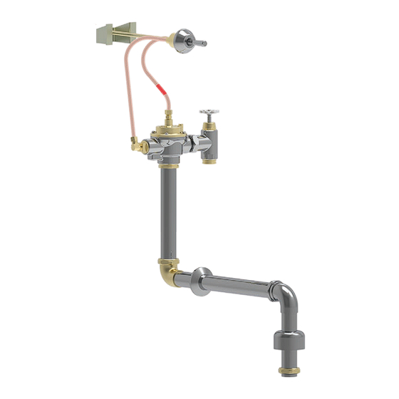
Step 2. FLUSHOMeteR ROUGH-IN INStALLAtION Figure 3 ÉtApe 2. INStALLAtION De LA pLOMBeRIe BRUte DU ROBINet De CHASSe D’eAU pASO 2. FLUSHOMeteR ROUGH-IN INStALLAtION 83T00 - 1½" (38 mm) FIP Water Closet, Back Spud (see Figure 3) 1. Assemble vacuum breaker components (E) into the 22.75" (578 mm) outlet tube (F). -
Page 9: 83T14 - 1½" (38 Mm) Wallhung Water Closet, Back Inlet (See Figure 4)
83T14 - 1½" (38 mm) Wallhung Water Closet, Back Inlet (see Figure 4) Figure 4 1. Assemble vacuum breaker components (E) into the 22.75” (578 mm) outlet tube (F). 2. Attach the 22.75" (578 mm) outlet tube (F) and vacuum breaker components (E) onto the flushometer body (D) secure with the coupling nut (G). -
Page 10: 83T24 - 1½" (38 Mm) Freestanding Water Closet, Back Inlet (See Figure 5)
83T24 - 1½" (38 mm) Freestanding Water Closet, Back Inlet (see Figure 5) Figure 5 1. Assemble vacuum breaker components (E) into the 22.75” (578 mm) outlet tube (F). 2. Attach the 22.75" (578 mm) outlet tube (F) and vacuum breaker components (E) onto the flushometer body (D) secure with the coupling nut (G). -
Page 11: 83T34 - 1½" (38 Mm) Water Closet, Top Inlet (See Figure 6)
83T34 - 1½" (38 mm) Water Closet, Top Inlet (see Figure 6) Figure 6 1. Assemble vacuum breaker components (E) into the 22.75" (578 mm) outlet tube (F). 2. Attach the 22.75" (578 mm) outlet tube (F) and vacuum breaker components (E) onto the flushometer body (D) secure with the coupling nut (G). -
Page 12: 83T43 - ¾" (19 Mm) Urinal, Back Inlet, Syphon Jet (See Figure 7)
83T43 - ¾" (19 mm) Urinal, Back Inlet, Syphon Jet (see Figure 7) Figure 7 1. Assemble vacuum breaker components (E) into the 10" (254 mm) outlet tube (F). 2. Attach the 10" (254 mm) outlet tube (F) and vacuum breaker components (E) onto the flushometer body (D) secure with the coupling nut (G). -
Page 13: Step 3. Supply Stop Installation (See Figure 8)
Step 3. SUppLY StOp INStALLAtION (see Figure 8) Figure 8 WARNING It is important to FLUSH and thoroughly CLEAN water lines to ELIMINATE contaminants (example - scale, sediment, gravel, cuttings, solder, etc.). 1.0" 1. The vertical centre line of the copper inlet tube (SO2 ) should be 4.75"... -
Page 14: Step 4. Controll Connections (See Figure 9)
Step 4. CONtROLL CONNeCtIONS (see Figure 9) Figure 9 On a NEW INSTALLATION, always flush the valve 4 or 5 times to CAUTION clean out supply line debris. It is also advisable where more than one flushometer is installed on a water line, to flush out the water piping through the last flushometer outlet of the pipeline. -
Page 15: Flush Volume Adjustment
FLUSH VOLUME ADJUSTMENT RÉGLAGE DU VOLUME DE CHASSE AJUSTE DEL VOLUMEN DE DESCARGA High flow supply lines may be required, with the supply stop opened one turn. NOTICE AVIS Des lignes d’alimentation à haut débit peuvent être nécessaires, avec l’arrêt d’alimentation ouvert d’un tour. AVISO Pueden ser necesarias líneas de suministro de gran caudal, con el tope de suministro abierto una vuelta. -
Page 16: Réglage Du Volume De Chasse
Flush Volume Adjustment Figure 10 (see Figure 10) The FIRST FLUSH should ELIMINATE all air from the flushometer. DO NOTICE NOT ADJUST flushometer based on the results of the first flush. 1. Use the handle/button (A-5) to trigger a flush sequence. 2. -
Page 17: Repair Parts
REPAIR PARTS PIÈCES DE RECHANGE REPUESTOS Page 17 - 32 216036, Rev. D... - Page 18 Consulte el manual de repuestos y mantenimiento de la válvula de descarga TECK® para obtener información y piezas adicionales. Las cantidades por paquete pueden variar. Consulte la sección de piezas de la lista de precios más reciente de grifos de Delta Commercial para conocer las cantidades actuales.
- Page 19 Consulte el manual de repuestos y mantenimiento de la válvula de descarga TECK® para obtener información y piezas adicionales. AVISO Las cantidades por paquete pueden variar. Consulte la sección de piezas de la lista de precios más reciente de grifos de Delta Commercial para conocer las cantidades actuales.
-
Page 20: Tableau 1 - Tableau De Configuration Capuchon/Goupille De Verrouillage/Diaphragme
Table 1 - Cap/Pin/Diaphragm Configuration Table Tableau 1 - Tableau de configuration capuchon/goupille de verrouillage/diaphragme Tabla 1: Tabla de configuración del tapón/pasador/diafragma Urinal - Adjustable Water Closet - Adjustable Urinoir - Réglable Toilette - Réglable Urinal - Ajustable Escusado - Ajustable 0.5 gpf (1.9 Lpf) 1.6 gpf (6.0 Lpf) Cap/Solenoid &... -
Page 21: Troubleshooting
Inlet filter may be partially or 2. Replace inlet filter if required. completely obstructed. “Inlet Filter Maintenance (see Figure 11)” on page 27 instructions. NOTICE If the issue persists, contact Delta Commercial Technical Service at 1-800-387-8277 (Canada). Page 21 - 32 216036, Rev. D... - Page 22 Handle cage is damaged or warner. “Control Maintenance (see Figure 14)” on page 30 at or around the instructions. handle. If the issue persists, contact Delta Commercial Technical Service at 1-800-387-8277 (Canada). NOTICE Page 22 - 32 216036, Rev. D...
- Page 23 “Entretien du filtre d’arrivée d’eau (voir Figure complètement obstrué. 11)” à la page 27 pour les instructions. AVIS Si le problème persiste, communiquez avec le service technique de Delta Commercial au 1-800-387-8277 (Canada). Page 23 - 32 216036, Rev. D...
- Page 24 30 pour les instructions. de la poignée ou autour de celle-ci. Si le problème persiste, communiquez avec le service technique de Delta Commercial au 1-800-387-8277 (Canada). AVIS Page 24 - 32 216036, Rev. D...
- Page 25 AVISO • Le recomendamos utilizar únicamente piezas de repuesto originales de Delta®. • NO UTILICE FUERZA EXCESIVA para cerrar el vástago de tope de entrada. RECOMENDAMOS hacer una descarga con la válvula de descarga mientras se cierra el tope de entrada. El ruido creado por el flujo de agua o el flujo que entra en la unidad se detendrá cuando se cierre la entrada de agua.
- Page 26 Problema Indicador Causa Solución Compruebe que el montaje del tapón se haya colocado correctamente en el Aunque se reparó la cuerpo. válvula de descarga, Se montó de manera incorrecta. El tornillo de regulación debe estar siempre en el mismo lado que el tope de NO funciona entrada.
-
Page 27: Maintenance
Instrucciones de limpieza Esta válvula de descarga de Delta Commercial está diseñada y fabricada de acuerdo con los más altos estándares de calidad y rendimiento. Con el cuidado adecuado, brindará años de servicio sin problemas. Se debe tener cuidado con la limpieza de este producto. Aunque el acabado es extremadamente duradero, los LIMPIADORES ÁCIDOS (por ejemplo, limpiadores diseñados específicamente para escusados y escusados de porcelana vítrea),... -
Page 28: Entretien De L'ensemble Capuchon Et Vis De Réglage
Cap/Solenoid & Regulating Screw Assembly Figure 12 Maintenance (see Figure 12) 1. Close the supply stop (V). 2. Remove the four screws (D-6) holding the cap assembly (D-3) to the flushometer body (D). 3. Remove the cap assembly (D-3) carefully not to damage the diaphragm assembly (D-7). -
Page 29: Entretien De L'assemble Du Diaphragme Et De L'assise
Diaphragm/Guide Assembly And Seat Maintenance Figure 13 (see Figure 13) 1. Close the supply stop (V). 2. Remove the four screws (D-6) holding the cap assembly (D-3) to the flushometer body (D). 3. Remove the cap assembly (D-3) carefully not to damage the diaphragm assembly (D-7). -
Page 30: Entretien De La Commande
Control Maintenance Figure 14 (see Figure 14) Control Option 0 Control Option 1 Control Option - 0 Option de contrôle 0 Option de contrôle 1 1. Close the supply stop. 2. Loosen the control assembly (A) by loosening the nut (C) and the flange (B) off of the wall to allow the wall flange (A-6) and anti-rotation pin (A-1) to rotate and be removed. -
Page 31: Limited Warranty
écrire ou nous transmettre un courriel, aux coordonnées fournies ci-dessus. contact-us © 2024 Masco Canada Lte. Pour obtenir de l’assistance technique, appelez le service technique de Delta Commercial au 1-800-387-8277 (Canada) ou 1-877-509-2680 (U.S.A.) 255068, Rev H Page 31 - 32... -
Page 32: Garantía Limitada
Garantía limitada de los grifos comerciales de Delta® Los productos comerciales Delta cubiertos bajo esta garantía incluyen: La serie comercial Partes y acabado ® TECK de Delta, la serie comercial HDF de Delta, la serie comercial DEMD™ y la serie de ®...
Need help?
Do you have a question about the TECK 83T Series and is the answer not in the manual?
Questions and answers