Advertisement
LOW
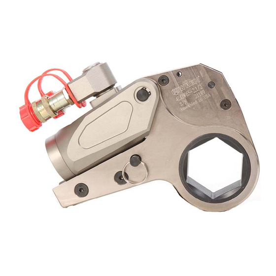
WREN HYDRAULIC TORQUE WRENCHES
LOW SERIES OPERATION AND MAINTENANCE MANUAL
FOR WREN 2LOW, 4LOW, 8LOW, 14LOW and 30LOW
LOW PROFILE HYDRAULIC TORQUE WRENCHES
Series 2LOW, 4LOW, 8LOW, 14LOW and 30LOW Low Profile Hydraulic Torque
Wrenches are designed for installing and removing large bolts having minimal
wrench clearance requiring precise high torque during bolt makeup and maximum
torque for bolt breakout.
It is necessary to read and understand this Operation and Maintenance Manual
when using WREN Hydraulic Torque Wrenches. The use of other than genuine
WREN replacement parts may result in safety hazards, decreased tool
performance, increased maintenance and may invalidate warranty.
Read this manual carefully before operating tool.
1
Advertisement
Table of Contents

Subscribe to Our Youtube Channel
Related Manuals for Wren LOW Series


Summary of Contents for Wren LOW Series
- Page 1 It is necessary to read and understand this Operation and Maintenance Manual when using WREN Hydraulic Torque Wrenches. The use of other than genuine WREN replacement parts may result in safety hazards, decreased tool performance, increased maintenance and may invalidate warranty.
-
Page 2: Safety First
Comply with the safety precautions to avoid personal injury or equipment damage while operating this tool! Neither WREN, nor its distributors are responsible for damage to the tool caused by unsafe and/or faulty operations. SAFETY FIRST! ▲... -
Page 3: Operation Section
▲ CAUTION DO NOT drop heavy objects, crush, or drive over the hydraulic hose assembly. A sharp impact may cause internal damage to the hose wire strands. Applying pressure to a damaged hose may cause it to rupture. A crushed hydraulic hose assembly should be replaced immediately. - Page 4 Preparation 1. Make certain of the size of the nut or bolt head, material, strength grade and determine the desired torque. Appendix I, which is presented as a guideline for comparison only, gives typical torque values specified for the most commonly encountered fasteners. Torque sequence may vary from manufacturer to manufacturer and even within individual factories, depending on the gasket material etc.
- Page 5 5. Setting for tightening or loosening the nut: The position of the tool relative to the nut determines whether the action will tighten or loosen the nut. The power stroke of the piston rod will always turn the hex ratchet toward the shroud. The nut turns clockwise for tightening and counterclockwise for loosening.
- Page 6 Coupler Placement Tool Advance Side-Male Retract Side-Female Hose Advance Side-Female to Female Retract Side-Male to Male Pump Advance Side-Male Retract Side-Female 7. Setting the pressure on the hydraulic power pack: To set the pressure on the pump, follow this procedure: a) Loosen the locking ring below the “T”...
- Page 7 Operation Before every operation, always read and follow the Operation Instructions. The Tightening Process: Operating the Hydraulic Torque Wrench 1) Place the ratchet link on the nut. Make certain it is the correct size for the nut and that the nut is fully engaged. Remove ratchet link from nut. 2) Attach ratchet link to power head and put on nut.
- Page 8 IMPORTANT: The reading of full preset pressure after the cylinder is extended DOES NOT INDICATE that this pressure (torque) is applied to the bolt/nut. It only indicates that the cylinder is fully extended and cannot turn the ratchet further until the tool automatically resets itself.
-
Page 9: Maintenance Section
3. Loosen the locking ring below the “T” handle on the hydraulic power pack external pressure regulator. Then, turn the “T” handle counterclockwise until it turns freely and easily. 4. When not in use, tools and accessories should be properly stored to avoid damage. -
Page 10: Troubleshooting Chart
TROUBLE-SHOOTING CHART SYSTEM PROBABLE CAUSE REMEDY Cylinder will not advance Couplers are loose or damaged Tighten Directional control valve on pump Replace Couplers not mated securely Tighten Cylinder will not retract See above See above Cylinder will not build pressure Piston seal leaks Replace seals Pump coupling may be broken, not mated... - Page 11 Disassembly of the Power Head 1. Make sure the hydraulic torque wrench is fully retracted. 2. Apply pressure to the hydraulic power head until the pressure reaches 2900-4300 psi (200-300kg/cm2), then remove the rod end (#28). 3. Remove the swivel. Inspect and replace the three O-rings. 4.
- Page 12 APPENDIX I...
- Page 13 LOW SPEC SHEET Model 2 LOW 4 LOW 8 LOW 14 LOW 30 LOW Torque (Ft-lbs.) 170 -1,700 430 - 4,320 800 - 8,000 1366 - 13,660 3050 - 30,500 1-5/16" - 2-5/8" - 1-9/16" - 3-13/16" - 3-1/8" - 6-5/16"...
- Page 14 LOW POWERHEAD DRAWING BREAKDOWN Drawing Number Description Housing Set Screw Piston End Cap Socket Head Cap Screw Set Screw Ring for Short Link Pin 360º Swivel Assembly Retaining Ring for Fixed Upper Pin Fixed Upper Pin Short Link Pin Rod End Set Screw With Ball Male Coupler Female Coupler...
Need help?
Do you have a question about the LOW Series and is the answer not in the manual?
Questions and answers