Table of Contents
Advertisement
Quick Links
Advertisement
Table of Contents

Related Manuals for ABB D13 15


Summary of Contents for ABB D13 15
- Page 1 Energy Meter D13 15 User manual...
-
Page 3: Table Of Contents
D13 METER USER MANUAL Table of Contents 1 General information....................5 1.1 Use and storage of the manual ................5 1.2 Copyright ........................5 1.3 Liability disclaimer ....................5 1.4 General safety warnings ..................5 1.5 Cyber Security Disclaimer ..................6 2 Technical characteristics ..................7 2.1 Product marking ......................7 2.2 Versions ........................9 2.3 Overall dimensions ....................9... - Page 4 D13 METER USER MANUAL 6.8 Setting Wires ......................37 6.9 Setting I-0 ......................38 6.10 Setting Alarm .......................39 6.11 Setting Tariff ......................41 6.12 Setting Modbus communication ..............41 6.13 Setting M-bus communication ................ 42 7 Technical meter functionalities ................43 7.1 Energy Values ......................43 7.2 Instrumentation functions .................
-
Page 5: General Information
The information contained in this document is subject to change without notice and cannot be considered as an obligation by ABB S.p.A. ABB S.p.A. is not liable for any errors that may appear in this document. ABB S.p.A. is not liable under any circumstances for any direct, indirect, special, incidental or consequential damage of any kind that may arise from using this document. -
Page 6: Cyber Security Disclaimer
ABB S.p.A. and its affiliates are not liable for damages and/or losses related to such security breaches, unauthorized access, interference, intrusion, leakage and/or theft of data or information. -
Page 7: Technical Characteristics
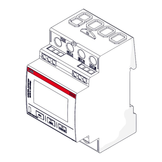
Esc from the menu (long press) Toggle up (short press) UP/HOMEpushbutton Enter configuration mode (long press) Terminal for input/output connection Terminal for communication connection Product label Product information Dangerous voltage Terminals description Serial number bar code QR Code link to ABB Energy meter web page... - Page 8 D13 METER USER MANUAL 2CMA241765R1000 Energy Meter D13 15-M 65 Modbus 3x220 / 380 Vac 3x240 / 415 Vac 0,25-5 (65) A 50/60 Hz 1.000 imp/kWh Cl. B (1) - Active Cl. 2 - Reactive Class II UC-2 Uimp 6 kV -40...+70°...
-
Page 9: Versions
D13 METER USER MANUAL 2.2 Versions The D13 15 meters versions are listed in the below table: Product name Certification Communication Accuracy Cl. 1 - Active D13 15 65 Cl. 2 - Reactive 1 Digital input D13 15-M 65 1 Digital output... -
Page 10: Main Functionalities
D13 METER USER MANUAL 2.4 Main functionalities Mechanical properties DIN modules Overall dimensions 65 x 97 x 52,5 mm Voltage/current inputs Direct connection Indirect connection via CT Indirect connection via VT Energy measurements Active energy Reactive energy Apparent energy ... -
Page 11: Technical Data
D13 METER USER MANUAL 2.5 Technical data Voltage/current inputs Nominal voltage 3 x 220/380 VAC 3 x 240/415 VAC Voltage range 3 x 220-240 VAC +/- 20% Power consumption voltage circuits 0.82 W maximum Power consumption current circuits 0.006 W per phase Base current Ib Reference current Iref Transitional current Itr... -
Page 12: Insulation Map
D13 METER USER MANUAL Digital Output Current 2…60mA Voltage 5…40 VDC (+/-10%) Max ON state drop Voltage 1,5V Pulse output frequency Prog. 1–999999 imp/MWh, 1–999999 imp/kWh, 1–999999 imp/Wh Pulse length 10–990 ms Insulation SELV Digital Input Max Voltage (absolute rating) 44 VDC Off state Voltage 0…5 VDC (+/-10%) -
Page 13: Installation
DIN-rail mounted The D13 15 meters are intended to be mounted on a DIN-rail (DIN 50022). If this method of mounting is used no extra accessories are needed and the meter is fastened by snapping the DIN-rail lock onto the rail. -
Page 14: Environmental Considerations
D13 METER USER MANUAL 3.2 Environmental considerations Ingress protection The product is for indoor use only. To comply with the protection requirements the product must be mounted in a fireproof meter cabinet with protection class IP 51 or better, according to IEC 60259. Mechanical environment In accordance with the Measuring Directive (2014/32/EU), the product complies with M2, which means that it can be operated in “...locations with significant or high levels of vibration and shock, e.g. - Page 15 D13 METER USER MANUAL Install the meter Follow the steps in the table below to install and verify the installation of the meter: Step Action Switch off the mains power. Place the meter on the DIN-rail and make sure it snaps onto it. Strip the cable insulation to the length that is indicated on the meter.
-
Page 16: Wiring Diagrams
D13 METER USER MANUAL 3.4 Wiring diagrams This section describes how to connect the meter to an electricity network. The terminal numbers in the wiring diagrams listed below correspond to the marking on the terminal block of the meter. In a case of MID meter, D13 will enter in MidLock once an energy consumption of 1kWh has been reached. When MidLock is reached, wiring settings can no longer be modified in accordance with the European MID directive. - Page 17 D13 METER USER MANUAL • 3-phase 3-wire connection (MID) • 2-phase 3-wire connection (No MID configuration) This configuration does not meet the MID certification (2014/32/EU directive).
- Page 18 D13 METER USER MANUAL • 1-phase 2-wire connection (MID) In order to meet the MID directive (2014/32/EU) only Line 1 shall be used. Input/Output • Input connection • Output connection generator generator generator Rout Iout Iout Vout OUT COM OUT COM OUT COM...
- Page 19 D13 METER USER MANUAL Communication RS485 - Modbus RTU version MBUS version A = Data - A = MBUS A B = Data + B = MBUS B C = Common C = Not used Terminal Connectors Line terminals Min. wire cross section 1 mm²...
-
Page 20: Configuring The Meter
D13 METER USER MANUAL 3.5 Configuring the meter Default settings For information about how to change the default settings of the meter, refer to “6 Configuration”. The following table lists the default meter settings: Parameter Direct connected meters Numbers of wires 3P4W: 3 phase 4 wires Pulse frequency 1.000 impulses / kWh (kvarh) -
Page 21: First Commissioning
D13 METER USER MANUAL 4 First commissioning At first power up of D13 15 energy meter, a wizard procedure will guide the user in the first commissioning steps. 4.1 Fast setup During fast setup, the user has to take one of the following choices: a) NOT perform the Fast Setup: In this case, the meter takes the following default parameters: •... - Page 22 D13 METER USER MANUAL Fast setup - Wires configuration In wires menu user can declare which is the meter’s wiring scheme applied. D13 will enter in MidLock once an energy consumption of 1kWh has been reached. When MidLock is reached, wiring settings can no longer be modified in accordance with the European MID directive. To perform the wires setting, please follow the following step: FAST SETUP...
- Page 23 D13 METER USER MANUAL Fast setup - Communication settings Second step of fast setup is related to communication parameters that vary depending on the meter’s type: • In a case of Modbus meter, the following steps have to be performed (“6.12 Setting Modbus communication”): MODBUS ADDRESS BAUD PARITY See the table below for details Modbus menu Address 1-247 Baud 115200 57600 38400 19200 9600 4800 2400 1200 Parity Even...
-
Page 24: Final Confirmation
D13 METER USER MANUAL • In a case of meter without Modbus or Mbus, the following steps have to be performed: PULSE See the table ALARM below for details DO menu Pulse Quant tot IMP kW h (Total Import Active energy) Quant tot EXP kW h (Total Export Active energy) Quant tot IMP k VArh (Total Import Reactive energy) Quant tot EXP k VArh (Total Export Reactive energy) Select and set the parameter (quantity) associated with Alarm the channel (see “6.10 Setting Alarm”). Fast setup - Password configuration In order to protect settings of your meter, a 4 digits password can be set (see “6.3 Setting Password”): 0--- 4.2 Final confirmation Once all fast setup settings are performed a confirmation is needed: CONFIRM MID: L OCK... -
Page 25: Access To Device
D13 METER USER MANUAL 5 Access to device 5.1 Button explanation Buttons Functions Press Hold Set/Confirm the value selected Scroll up/Increase a digit Return to the main menu Scroll down/Decrease a digit Return to the previous menu 5.2 Display structure The display structure is divided into 3 main areas, as shown in the figure below: 0000000 00000... -
Page 26: Menu
D13 METER USER MANUAL 5.3 Menu Pushing the screen shows the following pages: Icon Indication Home – Active import Home – Active export Home – Reactive import Home – Reactive export energy Energy INSTANT Instantaneous Values RST. R EG Reset Register TARIFFs Tariffs PWR. -
Page 27: Icons Description And Status
D13 METER USER MANUAL 5.4 Icons description and status Icon Description Status Communication is in progress. The meter is When communication is in progress the either sending “ ” or receiving “ ” information icon switch on Arrows indicate direction of current per phase. Arrow left = export A digit without arrow indicates that the current Arrow right = import... -
Page 28: Main Menu
D13 METER USER MANUAL 5.5 Main menu All data reading may be available in the display depending on wiring scheme (see “7.2 Instrumentation functions”). ENERGY INSTANT Active Energy Import Tot Active Power Tot Active Energy Import L1 Active Power L1 Active Energy Import L2 Active Power L2 Active Energy Import L3... - Page 29 D13 METER USER MANUAL TARIFF Active Energy Import T1 Output Type Active Energy Import T2 Output Status Active Energy Import T3 Input Type Active Energy Import T4 Pulse Counter Active Energy Export T1 Active Energy Export T2 LOGS Active Energy Export T3 Active Energy Export T4 Reactive Energy Import T1 Alarms...
-
Page 30: Configuration
D13 METER USER MANUAL 6 Configuration This chapter gives an overview of the meter settings and configuration. 6.1 Menu structure All or a subset of the following functions can be configured: Fast Setup (Only the first time) Set/Modify Password Reset Factory Global Resettable registers (Rst.Rg on display) -
Page 31: Setting A Value
D13 METER USER MANUAL 6.2 Setting a value Buttons Functions Press Hold Set/Confirm the value selected Scroll up/Increase a digit Return to the main menu Scroll down/Decrease a digit Return to the previous menu Setting a number procedure Link Description The menu requires the entry of numerical characters (0-9). - Page 32 D13 METER USER MANUAL The option/digit that is active for setting is flashing. When the flashing on the last option has stopped, the setting has been performed. Example: flashing option Example: flashing digit 0--- After configuring a setting, a confirmation screen always appears. Press to make the change definitive.
-
Page 33: Setting Password
D13 METER USER MANUAL 6.3 Setting Password • Activate/deactivate password SETTING • Modify password SETTING MODIFY 0--- Insert the new password (previously the device ask the old password if it was configured). -
Page 34: Reset Options
D13 METER USER MANUAL 6.4 Reset options SETTING RESET FACTORY GLOBAL RES. R EG See the table LOG. R ES below for details Reset options Restore the device to the factory state, except for the Factory reset audit log, and wiring scheme in a case of MID meter Complete reset of the device except for the settings Global reset and the audit log... -
Page 35: Setting Standby Options
D13 METER USER MANUAL 6.5 Setting Standby options The meter allows to set the time interval necessary for the device to enter standby and the brightness maintained by the device once it enters this phase. To change these parameters, perform the following steps: •... -
Page 36: Setting Autoscroll Options
D13 METER USER MANUAL 6.6 Setting Autoscroll options The device is equipped with an Autoscroll feature that can be activated or deactivated. It is also possible to set the time interval necessary for the automatic scroll to take place. To set this options, perform the following steps: •... -
Page 37: Setting Currency/Co2
D13 METER USER MANUAL 6.7 Setting Currency/CO2 The device allows to set a conversion factor for Currency/CO2 , consequently kWh is converted to currency and/or kg CO2. SETTING CO2-CUR 0---- CO2 range: 1 - 9999 Kg/kWh CUR range: 1 - 999999 Cur/kWh 6.8 Setting Wires To set the number of wires and the type of wiring, perform the following steps (it is possible until 1kWh is reached in MID version):... -
Page 38: Setting I-0
D13 METER USER MANUAL 6.9 Setting I-0 SETTING See the table below for details Once you selected the parameter associated with the pulse output the meter will ask to select the pulse frequency (seconds) and the pulse lenght. Digital Output Options Pulse Active energy import Active energy export... -
Page 39: Setting Alarm
D13 METER USER MANUAL 6.10 Setting Alarm “7.3 Alarm” for alarm definition. The meter allows to set up alarms on up to 25 different channels, connected to a selectable parameter. The procedure is the same for each of the 25 channels. To configure Alarms, perform the following steps: SETTING Alarm 1. - Page 40 D13 METER USER MANUAL 3. Select the alarm type, the available options are Cross up and Cross down. 4. Select the threshold value connected to the activation of the alarm, depending on the alarm type. 0---- cross up value cross down 5.
-
Page 41: Setting Tariff
D13 METER USER MANUAL 6.11 Setting Tariff “7.4 Inputs and Outputs” for further details. SETTING TARIFF input comm 6.12 Setting Modbus communication SETTING MODBUS ADDRESS BAUD PARITY See the table below for details Modbus menu Address 1-247 Baud 115200 57600 38400 19200 9600... -
Page 42: Setting M-Bus Communication
D13 METER USER MANUAL 6.13 Setting M-bus communication SETTING MBUS ADDRESS BAUD Access See the table below for details M-Bus menu Address 1-250 Baud 38400 19200 9600 2400 Access Level Open Open with password Close... -
Page 43: Technical Meter Functionalities
D13 METER USER MANUAL 7 Technical meter functionalities This chapter contains technical descriptions of the meter functions. 7.1 Energy Values The energy values are stored in energy registers. The different energy registers can be divided into: • Registers containing active, reactive or apparent energy •... -
Page 44: Alarm
D13 METER USER MANUAL Instrumentation 3-phase, 4-wire 3-phase, 3-wire 2-phase, 3-wire (No MID) 1-phase, 2-wire Current quadrant, Total Current quadrant, L1 Current quadrant, L2 Current quadrant, L3 Accuracy All instrumentation data accuracy is defined within the voltage range 20 % of the stated nominal voltage and within the current range 5 % of the base current to the maximum current. -
Page 45: Inputs And Outputs
D13 METER USER MANUAL Functional description When the value of the monitored quantity passes the reference value for a period of time equal or longer than the specified time delay, the alarm is activated. In the same way, the alarm is deactivated when the value passes the deactivation level and remains there for a time equal or longer than the specified time delay. - Page 46 D13 METER USER MANUAL Pulse Outputs On the pulse outputs the meter sends out a specified number of pulses (pulse frequency) per kWh (kvarh for reactive pulse outputs). The output can be controlled by communication or alarm. The number of pulses is proportional to the energy passing through the meter and length of pulses. Pulse frequency and pulse length can be set via the pushbuttons on the meter or via communication.
-
Page 47: Logs
D13 METER USER MANUAL 7.5 Logs The D13 meter contains two types of different logs: • Event Log • Audit Log Event Log Event Log include Error, Warning and Alarm. Event Log can be read via communication or directly in the display of the meter. A maximum of 200 log events can be stored in the Event Log When the maximum number of events for a log is reached, the oldest events will be overwritten. - Page 48 D13 METER USER MANUAL • Alarm • Alarm Current L1 • Alarm Current L2 • Alarm Current L3 • Alarm Current Neutral • Alarm Active Power Total • Alarm Active Power L1 • Alarm Active Power L2 • Alarm Active Power L3 •...
-
Page 49: Measurement Methods
D13 METER USER MANUAL 8 Measurement methods This chapter contains information about measurement theory and the most common used measurement methods. The information can be used to better understand the meter behavior and/or to pick the correct measurement method. 8.1 Measuring Energy and power Active energy It is easy to understand the need for a utility to measure active energy, since the information is necessary to bill the customer correctly. - Page 50 D13 METER USER MANUAL Active power Active power is calculated by continuosly taking snapshots of the active energy measured and dividing the energy increment with the time passed between the snapshots, see formula below where Ek and Ek+1 are two successive active energy snapshots and T is the time passed between the snapshots, where T is a complete number of mains line cycles.
- Page 51 D13 METER USER MANUAL Apparent energy Apparent energy is calculated as a summation of all measured elements as the product of voltage and current rms values and the rms measurement time T, which is a number of complete mains line cycles, see formula below.
- Page 52 D13 METER USER MANUAL Phase displacement A load that consumes both reactive and active energy can be divided into active and reactive components. The angle between the apparent power (U*I) vector and the active power component is described as phase displacement angle or power factor angle. The illustration below shows a vector diagram for a load with an active and a reactive component with no harmonics present.
- Page 53 D13 METER USER MANUAL The 4 power quadrants The type of load can be represented geometrically by for quadrants. In the first quadrant the load is inductive and active and energy is imported (energy is delivered from the utility to the customer). In the second quadrant the load is capacitive and active energy is exported and reactive energy is imported.
-
Page 54: Single Phase Metering
D13 METER USER MANUAL 8.2 Single phase metering Single phase metering in a 2-wire system In a 2-wire installation a single phase meter is used. Normally the 2 wires are a phase voltage and the neutral. The active energy consumed by the load is the product of momentary voltage and current integrated over the desired measuring time period. -
Page 55: 3-Phase 3-Wire Metering
D13 METER USER MANUAL 8.3 3-Phase 3-wire metering The 3-phase 3-wire metering method is used in systems with 3 wires, normally a 3-phase system that does not have a neutral conductor. 3-phase 3-wire metering can be used irrespectively of the load being balanced or not. -
Page 56: 3-Phase 4-Wire Metering
D13 METER USER MANUAL 3-phase 3-wire metering in a 4-wire system 3-phase 3-wire metering can also be used in a 4-wire system if the current in the neutral connection is zero. Applying this method in a system having a non-zero neutral current will decrease the accuracy, but can sometimes be justified if the current is small compared to the line currents or if high accuracy is not required. -
Page 57: Service & Maintenance
This product contains no parts that can be repaired or exchanged. A broken meter must be replaced. If you need assistance please contact ABB. Do not open the meter case and do not attempt to repair any component. Opening the meter will void accuracy and calibration. -
Page 58: Cleaning
D13 METER USER MANUAL WARNING_PHASE1_CONNECTED_TO_NEUTRAL, LOG_WARNING_PHASE1_ tO_NEUt, PHASE1 1021 CONNECTED_TO_NEUTRAL WARNING_PHASE2_CONNECTED_TO_NEUTRAL, LOG_WARNING_PHASE2_ tO_NEUt, PHASE2 1022 CONNECTED_TO_NEUTRAL WARNING_PHASE3_CONNECTED_TO_NEUTRAL, LOG_WARNING_PHASE3_ tO_NEUt, PHASE3 1023 CONNECTED_TO_NEUTRAL WARNING_PULSES_MERGED_1, LOG_WARNING_PULSES_MERGED_1 MErgEd, PULSE1 1024 WARNING_PULSES_MERGED_2, LOG_WARNING_PULSES_MERGED_2 MErgEd, PULSE2 1025 WARNING_POWERFAIL, LOG_WARNING_POWERFAIL POWEr, FAIL 1030 Alarm Codename-description Text [Row1,Row2] Code ALARM_1_ACTIVE, LOG_ALARM_1 ALArM, 1... -
Page 59: Communication Manual
D13 METER USER MANUAL 10 Communication manual 10.1 QR Code D13 Communication manual... - Page 60 ......................................................................................................................................................................................................................................................................................................................................................................................................................................................................................................................................................................................................................................................................................................................................................................................................................................................................................................................................................................................................................................................................................................................................................................................................................................................................................................................................................................................................................................................................................................................................................................................................................................................................................................
- Page 61 ......................................................................................................................................................................................................................................................................................................................................................................................................................................................................................................................................................................................................................................................................................................................................................................................................................................................................................................................................................................................................................................................................................................................................................................................................................................................................................................................................................................................................................................................................................................................................................................................................................................................................................................
- Page 62 ......................................................................................................................................................................................................................................................................................................................................................................................................................................................................................................................................................................................................................................................................................................................................................................................................................................................................................................................................................................................................................................................................................................................................................................................................................................................................................................................................................................................................................................................................................................................................................................................................................................................................................................
- Page 63 ......................................................................................................................................................................................................................................................................................................................................................................................................................................................................................................................................................................................................................................................................................................................................................................................................................................................................................................................................................................................................................................................................................................................................................................................................................................................................................................................................................................................................................................................................................................................................................................................................................................................................................................
- Page 64 ABB S.p.A Electrification business Viale dell’Industria, 18 20009 Vittuone (MI) Italy new.abb.com/low-voltage...
Need help?
Do you have a question about the D13 15 and is the answer not in the manual?
Questions and answers