Table of Contents
Advertisement
Quick Links
Advertisement
Table of Contents

Subscribe to Our Youtube Channel
Related Manuals for SWM Binsen


Summary of Contents for SWM Binsen
-
Page 2: Table Of Contents
User Manual-Operation- Maintenance BINSEN INDEX Chapter 1 Safety instruction -------------------- 6 2.10 Battery set ------------------------------- 23 1.1 Safety precautions -------------------------- 7 2.11 Steering lock ----------------------------- 28 1.2 Safe riding rules ---------------------------- 8 2.12 Side stand ------------------------------- 28 1.3 Refitting ----------------------------------- 9 Chapter 3 Operating instructions --------------- 29 1.4 Accessories -------------------------------- 9... - Page 3 User Manual - Operation - Maintenance BINSEN 4.7 Front wheel -------------------------------- 58 8.4 Labor-hour ------------------------------- 82 4.8 Rear wheel -------------------------------- 60 8.5 Limitation --------------------------------- 83 4.9 Tyre -------------------------------------- 62 8.6 Warranty exclusions ------------------------ 84 4.10 Chain ------------------------------------ 63 8.7 After-sales service and warranty coverage ------ 86 4.11 Side stand -------------------------------- 64...
- Page 4 Welcome to SWM electric motorcycle - Binsen family! The design and manufacture of your Binsen electric motorcycle is the best of its kind in the world. This user manual is designed to provide you with a guide to the proper operation and maintenance of this model. Please follow these instructions carefully to enjoy the best riding experience.
- Page 5 User Manual - Operation - Maintenance BINSEN Please read the user manual carefully before riding with Binsen, which contains certain information and advice to have a comfortable and safe riding experience. Please pay special attention to the precautions with the following...
- Page 6 Improper use or disposal may have an impact on the environment and human health. 2. This user manual is applicable for Binsen, both on-road and off-road version.
-
Page 7: Chapter 1 Safety Instruction
User Manual - Operation - Maintenance BINSEN Chapter 1 Safety instruction... -
Page 8: Safety Precautions
User Manual-Operation- Maintenance BINSEN 1.1 Safety precautions I. For your safety riding, always wear suitable protective clothing, safety helmet, protective mask, dust glasses, gloves and other protective equipment. II. Don’t wear loose clothes, which may easily hook onto the lever, pedal or wheel and cause danger. -
Page 9: Safe Riding Rules
User Manual - Operation - Maintenance BINSEN 1.2 Safe riding rules F. Strictly obey local traffic rules A. Check the condition of the bike and components Always ride within the prescribed speed limit range. based on the user manual before starting. -
Page 10: Refitting
User Manual-Operation- Maintenance BINSEN 1.3 Refitting 1.5 Part replacement It is illegal to refit the electric motorcycle or replace with Replace with official original parts when necessary. non-original part casually, which cannot guarantee the 1.6 Loading safety of electric motorcycle riding. Users must comply with the traffic management department's regulations on the use of electric motorcycle. -
Page 11: Chapter 2 Bike Details
User Manual - Operation - Maintenance BINSEN Chapter 2 Bike details... -
Page 12: Identification Data
User Manual-Operation- Maintenance BINSEN 2.1 Identification data 2.1.1 Vehicle identification number 2.1.2 Motor serial number The vehicle identification number is stamped on the The motor serial number is stamped on the up side of right side of the steering pipe. -
Page 13: Main Parts
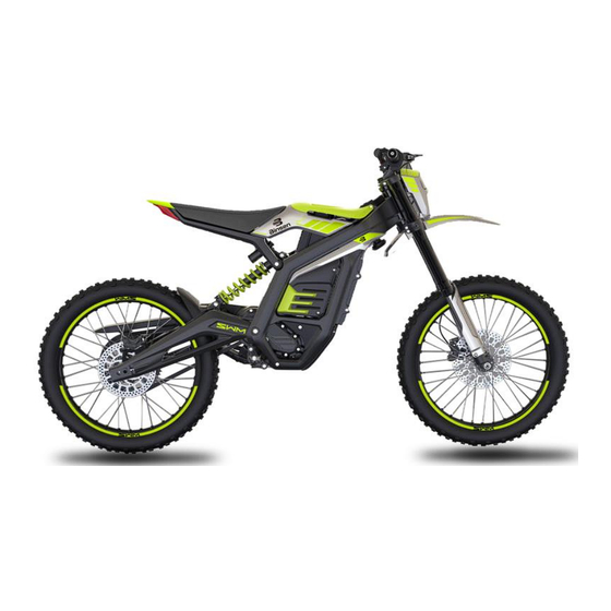
User Manual - Operation - Maintenance BINSEN 2.2 Main parts 2.2.1 Binsen - off-road version Saddle Lock assy Head light Front suspension Rear wheel Battery Front wheel... - Page 14 User Manual-Operation- Maintenance BINSEN Front fender Upper cover Battery holder Rear shock absorber Motor Side stand Rear fork...
- Page 15 User Manual - Operation - Maintenance BINSEN Rear brake lever Rear brake upper master cylin- Handlebar Dashboard Front brake upper master Front brake lever Left handle grip Left handle switch Right handle switch Right handle grip...
- Page 16 User Manual-Operation- Maintenance BINSEN 2.2.2 Binsen - on-road version Rear mudguard Saddle Lock assy Head light Front suspension Rear license bracket Rear wheel Frame Front wheel...
- Page 17 User Manual - Operation - Maintenance BINSEN Front fender Upper cover Battery holder Rear shock absorber Motor Side stand Rear fork License plate light...
- Page 18 User Manual-Operation- Maintenance BINSEN Rear view mirror LH Rear brake lever Rear brake master cylinder Handlebar Dashboard Front brake master cylinder Front brake lever Rear view mirror RH Left handle grip Left handle switch Right handle switch Right handle grip...
-
Page 19: Dashboard
User Manual - Operation - Maintenance BINSEN 2.3 Dashboard Dashboard function A. Mode: Sport mode, ECO mode; B. Battery: Remaining battery capacity display; C. Trip: Mileage subtotal display, max. 999.9km; D. Mileage: Total milage display, max. 99999km. It will remains displaying the max. value if real mileage exceeds;... -
Page 20: Ignition Switch
User Manual-Operation- Maintenance BINSEN 2.4 Ignition switch Danger To switch on/off the motor. Do not switch the key during riding. All circuits Key position Function Note will be cut off if the key is in “ “ position. ... -
Page 21: Rear Brake Lever
User Manual - Operation - Maintenance BINSEN 2.5 Rear brake lever 2.6 Front brake lever Hold the rear brake lever to operate the rear brake. The Hold the front brake lever to operate the front brake. brake light will be activated. -
Page 22: Left Handle Switch
User Manual-Operation- Maintenance BINSEN 2.7 Left handle switch A. Horn button: When the ignition switch is in the starting position, press the horn button to sound the horn. The electric motor- Mode switch cycle is quiet when riding, use the horn to warn pedes- trians or other motorists when necessary. -
Page 23: Right Handle Switch
User Manual - Operation - Maintenance BINSEN 2.8 Right handle switch 2.9. Throttle handle “P” mode switch Rotate the throttle handle to accelerate. To enter/exit from “P” mode. Throttle handle P button... -
Page 24: Battery Set
User Manual-Operation- Maintenance BINSEN 2.10 Battery set A. Battery function & illustration. Function Illustration Battery enters doze mode in 10s if all following condition are met: 1. Battery is not in discharging state (no ACC signal) 2. Battery is not in charging state (no CIN signal) 3. - Page 25 User Manual - Operation - Maintenance BINSEN B. Assembly and disassembly of the battery set 1) Open the top cover⑤: Press the top cover⑤ when ⑤ the key is in off position. Turn the key counter clock- wise until a click sound from the buckle and rise up the cover;...
- Page 26 User Manual-Operation- Maintenance BINSEN C. Charging 1) Open the top cover⑤: Press the top cover⑤ when ⑤ the key is in off position. Turn the key counter clock- wise until a click sound from the buckle and rise up the cover;...
- Page 27 User Manual - Operation - Maintenance BINSEN D. Battery display The display content includes remaining battery, total voltage of battery set and error code. Button Button press during Display method Display content operate displaying Automatic loop Display remaining battery, total voltage and error with...
- Page 28 User Manual-Operation- Maintenance BINSEN Display content Definition Illustration Status Of Capacity Remaining battery capacity Battery overvoltage Battery undervoltage Battery overcurrent Battery high temperature Battery low temperature ERROR 01 Battery malfunction ERROR 02 Motor malfunction ERROR 03 Controller malfunction ERROR 04...
-
Page 29: Steering Lock
User Manual - Operation - Maintenance BINSEN 2.11 Steering lock 2.12 Side stand Steering lock ① is integrated with ignition lock. To lock This bike is equipped with side stand ① and side the steering: stand sensor ②. A. Hold the handlebar and rotate counterclockwise. -
Page 30: Chapter 3 Operating Instructions
User Manual-Operation- Maintenance BINSEN Chapter 3 Operating instructions... -
Page 31: Riding Preparation
User Manual - Operation - Maintenance BINSEN 3.1 Riding preparation D. Tyre: Check if the tyres are worn out. Tyres with scratches or dents should be replaced, and the tread Follow the steps to check the bike before each riding: depth should comply with regulations. - Page 32 User Manual-Operation- Maintenance BINSEN F. Throttle handle: Check the throttle handle with the key in the off position. Rotate and release the handle to check the smoothness and stability. G. Lights and horn: Check if the lights and horn are working well.
-
Page 33: Riding Operation
User Manual - Operation - Maintenance BINSEN 3.2 Riding operation A. Starting 1) Turn the key clockwise; 2) Retract the side stand; 3) Hold the (front or rear) brake and short press the button P. When “Ready” displays on the dashboard, it’s ready to ride. - Page 34 User Manual-Operation- Maintenance BINSEN C. Park mode logic Park mode is activated if any of the following conditions are met: 1) The default state after power on is park mode. 2) No operation (no brakes) and no current output within 30s, park mode activates automatically.
-
Page 35: Tcs Disable
User Manual - Operation - Maintenance BINSEN 3.3 TCS disable Attention A. Operate the bike in starting status, the dashboard TCS is enabled by default; shows Ready, and the bike is stationary; TCS default mode goes with every time switch- B. -
Page 36: Motor Shut-Off With Rear Brake - Disable
User Manual-Operation- Maintenance BINSEN 3.4 Motor shut-off with rear brake - disable A. Place the bike in “Ready” state and stationary; B. Hold the right hand lever (front brake lever); C. Switch EP/Sport button 4 turns and wait for 2 sec- onds. -
Page 37: Energy Recovery Mode Switch
User Manual - Operation - Maintenance BINSEN 3.5 Energy recovery mode switch A. Place the bike in “Ready” state and stationary; The above operation must be finished within 2 B. Hold the right hand lever (front brake handle); minutes after the bike is switched-on. -
Page 38: Operation After Driving
User Manual-Operation- Maintenance BINSEN 3.6 Operation after driving Attention Please charge the battery pack in time after use of the To maximize battery pack life, please charge the electric motorcycle. Please disconnect the charger and battery pack immediately after each riding, be- the power supply after charging. -
Page 39: Chapter 4 Maintenance
User Manual - Operation - Maintenance BINSEN Chapter 4 Maintenance... - Page 40 Warranty services or other reasons for repairs, settings, or replacement of parts, all operations must be carried out at an official dealer network recognized by SWM.
- Page 41 User Manual - Operation - Maintenance BINSEN Regular inspection and maintenance Inspection item Check list Battery Voltage, charging port, etc., and check if there is any fault code Motor Check if the motor is in good condition Important parts check and mainte-...
- Page 42 User Manual-Operation- Maintenance BINSEN Continued Lights Irradiation position, angle, circuit and insulation Rear view mirror Rear view angle, range, screw fastening Front and rear tyres Tyre pressure, tyre wear Brake system Brake oil, brake disc, brake pads...
-
Page 43: Battery
User Manual - Operation - Maintenance BINSEN 4.1 Battery Danger A. Remaining battery capacity Don't use the battery in an environment beyond This electric motorcycle uses a sealed ternary lithium the waterproof level. The internal waterproof of battery. The battery needs to be fully charged before the battery may fail under changes in environ- checking. - Page 44 User Manual-Operation- Maintenance BINSEN Don't use metal objects such as wires to directly It is prohibited to mix with other batteries be- connect the positive and negative terminals of cause they have different capacity, chemical the battery to avoid short-circuit.
- Page 45 User Manual - Operation - Maintenance BINSEN please don't rub the eyes. Wash the eyes with wa- Don't use the battery in the electrostatic environ- ter immediately and seek for medical attention ment where the power generation exceeds 1000V, immediately.
- Page 46 User Manual-Operation- Maintenance BINSEN If the battery circuit terminal is dirty, wipe it with a dry cloth before use, otherwise it may affect the performance due to poor contact. Store the battery at room temperature, with ca- pacity charged to 30%~60%. To prevent overdis-...
-
Page 47: Charger
User Manual - Operation - Maintenance BINSEN 4.2 Charger F. Charge with the original charger delivered or equiva- A. The indicator of the charger turns to red while charg- lent charger from the original manufacturer. Different ing, and turns to green after full charge. If it remains in... -
Page 48: Motor
User Manual-Operation- Maintenance BINSEN 4.3 Motor Attention A. General check Motor to be stored in a ventilated and dry place, not 1) Regularly check the tightness of the screws. in wet acid and alkali conditions, and should not be 2) Regularly check the connection between the motor stored with magnetic items. - Page 49 User Manual - Operation - Maintenance BINSEN B. Motor oil replacement Attention 1) Switch off the ignition key. Remove the lower pro- The first motor oil replacement cycle is 3000km, and tection ③. the subsequent cycle is 5000km. 2) Put a container right below the oil draining screw ②...
-
Page 50: Brake System
User Manual-Operation- Maintenance BINSEN 4.4 Brake system The front and rear brakes are disc brakes. Due to the wear of brake pads, the brake fluid will decrease over time. Brake fluid level and friction plate wear are the two most important factors need to be checked. - Page 51 User Manual - Operation - Maintenance BINSEN B. Brake pads The wear of brake pads is related with driving conditions. Especially on damp and muddy roads, it is more prone to wear. It is recommended for an after-sales service for maintenance every three months.
- Page 52 User Manual-Operation- Maintenance BINSEN C. Brake oil Brake oil level check The brake oil cup is connected to the oil pump. There is a scale line on the transparent glass. Place the oil cup in a horizontal position, and the oil level should not be lower than the lower scale line.
- Page 53 User Manual - Operation - Maintenance BINSEN D. Brake disc Brake disc must be replaced if it’s thickness is less than 2.5mm: 1) Refers to the relevant process to disassemble the front wheel (4.7) and rear wheel (4.8). 2) The tightening torque for the brake disc screw is...
-
Page 54: Suspension System
User Manual-Operation- Maintenance BINSEN 4.5 Suspension system It is recommended to clean the surface of suspensions Warning immediately after each riding, especially the sediment Improper operation of the suspension may cause attached to the surface of the main pipe. When cleaning... - Page 55 User Manual - Operation - Maintenance BINSEN A. Front suspension Compression damping Rebound damping Turn the screw ① on the left suspension to adjust the Turn the screw ② on the right suspension to adjust the compression damping. rebound damping.
- Page 56 User Manual-Operation- Maintenance BINSEN B. Rear shock absorber Attention Pre-load adjustment steps: The damping and spring pre-load should be rea- Release the spring lock ① with adjusting wrench; sonably adjusted according to the road condi- Turn the adjusting ring ② with adjusting wrench;...
- Page 57 User Manual - Operation - Maintenance BINSEN Rebound damping Compression damping Turn the screw ③ at the bottom of the shock absorber Turn the screw ④ at the top of the shock absorber to to adjust the rebound damping. adjust the compression damping.
-
Page 58: Headlight
User Manual-Operation- Maintenance BINSEN 4.6 Headlight Regularly check if the headlight angle is correct. Head- 4) Turn the screw ① until the correct beam angle is light angle must be re-adjusted after changing the an- reached; gle of the bike at any time, because angle change of the 5) With the correct irradiation angle, the cutoff line of bike will affect the angle of the headlight. -
Page 59: Front Wheel
User Manual - Operation - Maintenance BINSEN 4.7 Front wheel Warning A. Dismounting Do not hold the front brake lever while dis- Place a lifting platform under the motor. Rise the plat- mounting the front wheel. form to lift the front wheel. Unfasten the screw ① and ... - Page 60 User Manual-Operation- Maintenance BINSEN D. Front wheel axle check Warning Place the front wheel axle on a V-shape platform. Find an official dealer for correction if the max. tightening torque can’t be reached to ensure a Check the deflection with dial gauge. Replace the front stable bearing for riding.
-
Page 61: Rear Wheel
User Manual - Operation - Maintenance BINSEN 4.8 Rear wheel A. Dismounting Place a lifting platform under the motor. Rise the plat- form to lift the rear wheel. Unfasten the screw ① and ②. Pull the rear wheel axle ③ until the rear wheel can be pushed back. - Page 62 User Manual-Operation- Maintenance BINSEN B. Mounting C. Rear wheel bearing check Reverse the dismounting process. Check if the bearing is damaged or wore. Replace the bearing if necessary. Tight the axle screw with torque 72~78N.m. Place the rear wheel on the correction platform to Tight the tensioner screw with torque 8~12N.m.
-
Page 63: Tyre
User Manual - Operation - Maintenance BINSEN 4.9 Tyre Standard tyre pressure State Front tyre Rear tyre Tyres on a new bike are lack of ground adhesion. In this Off-road tyre 2.25 Bar 2.25 Bar case, new bike should be ridden with appropriate speed... -
Page 64: Chain
User Manual-Operation- Maintenance BINSEN 4.10 Chain 5) Fasten the rear axle nut ①; 6) Fasten the left and right lock nuts ③ to secure the Keep the chain and sprocket clean. adjustment bolts ②; 7) Apply a proper amount of chain oil. -
Page 65: Side Stand
User Manual - Operation - Maintenance BINSEN 4.11 Side stand 4.13 Steering Check if the side stand rotates smoothly. Clean the axle Rise the front wheel with a lifting platform placed un- area if there’s stiffness or abnormal sound. Apply with der the motor. -
Page 66: Cable Rubber
User Manual-Operation- Maintenance BINSEN 4.15 Cable rubber 4.16 Bike cleaning As a cable protection, the cable rubber. Do not flush 1) Clean the bike with sponge or a soft cloth with neu- water against the cables when you clean the vehicle. - Page 67 User Manual - Operation - Maintenance BINSEN Attention Warning Some parts on the bike may be damaged by im- After every cleaning, the brake system must be proper cleaning. Don't use high-pressure water checked before riding. gun to flush bearings, seals, electrical compo- nents and plugs.
-
Page 68: Long-Term Storage
User Manual-Operation- Maintenance BINSEN 4.17 Long-term storage Attention If the motorcycle will not be used for a long period Don't store the electric motorcycle with less than (more than 30 days), it is recommended to consume the 30% of the remaining battery capacity, which will... -
Page 69: Chapter 5 Main Technical Parameters
User Manual - Operation - Maintenance BINSEN Chapter 5 Main technical parameters... -
Page 70: Vehicle Parameters
Frame Aluminum Permanent magnet synchronous Power train Controller Vector sine wave motor + reducing gearbox Unladen weight Version Max. speed Reference mass (Battery included) Binsen - off-road 80Km/h 51Kg/63kg 138 Kg Binsen - on-road 45 Km/h 53 Kg/65kg 140 Kg... -
Page 71: Battery Technical Parameters
User Manual - Operation - Maintenance BINSEN 5.2 Battery technical parameters 5.2.1 General parameter Cell type INR21700-5Ah Nominal voltage Min. capacity 28.5Ah@1C/25℃/discharge Nominal power 2160Wh Voltage range 58~84V Standard charging current 6A(0.2C) Max. charging current 15A(0.5C) Continuous discharge current Max.discharging current... - Page 72 User Manual-Operation- Maintenance BINSEN Continued Working temperature for charging 0 to 45℃ Working temperature for discharging -20 to 60℃ Storage temperature 0 to 45℃ Storage period 6months@SOC35%@0~45℃ 600 (≥60%SOC@25±5℃) Cycle life (times) 12A charging & 60A discharging Humidity < 85 % RH Battery capacity reserve for transport >...
- Page 73 User Manual - Operation - Maintenance BINSEN 5.2.2 Protection parameter Protec- Recovery Function tion Delay Tech requirement parameter rameter Total voltage over-voltage Error info display. ≥84V ≤82V protection Charging disabled. Total battery low-voltage Error info display. ≤58V ≥60V protection Discharging disabled.
- Page 74 User Manual-Operation- Maintenance BINSEN Continued Protec- Recovery Function tion pa- Delay Tech requirement parameter rameter Auto- matic re- Short-circuit protection ≥667A 320μs lease af- Discharging disabled. ter load removal Error info display. MOS high temperature ≥85℃ ≤75℃ Charging/discharging disa- protection bled.
-
Page 75: Chapter 6 Electrical Schematic Diagram
User Manual - Operation - Maintenance BINSEN Chapter 6 Electrical schematic diagram... - Page 76 User Manual-Operation- Maintenance BINSEN...
-
Page 77: Chapter 7 Troubleshooting
User Manual - Operation - Maintenance BINSEN Chapter 7 Troubleshooting... - Page 78 User Manual-Operation- Maintenance BINSEN Fault Analysis Action The power supply is damaged or the Check the ignition lock and plug-in. Repair or replace if neces- plug-in is in poor contact sary. The power plug is in poor contact Check ignition lock plug and socket. Repair or replace if neces- with the battery socket sary.
- Page 79 User Manual - Operation - Maintenance BINSEN Continued Fault Analysis Action Side stand switch protection Retract the side stand Side stand switch damaged Disconnect or replace the side stand switch Power-off-with-brake switch protection Check brake switch Power-off-with-brake switch is dam-...
- Page 80 User Manual-Operation- Maintenance BINSEN Continued Fault Analysis Action Motor doesn't work Motor poor connection Re-connect the motor cable with normal power Brake lever not returned or sensor failure Check the brake lever and brake sensor supply Fallen protection activated Re-start the bike...
-
Page 81: Chapter 8 Warranty And Service Booklet
User Manual - Operation - Maintenance BINSEN Chapter 8 Warranty and service booklet... -
Page 82: Warranty Conditions
8.2 Warranty period During the period, warranty covers all new vehicles A. Common use purchased from dealers authorized by SWM with de- Period: 12 months from the date of purchase or 10000 fects in materials and technology, certain limitations as kilometers of travel mileage, whichever comes first. -
Page 83: Parts Covered By Warranty
8.4 Labor-hour Defects found in the vehicle warranty components which requires manual repairing/replacement, the la- bor cost will be borne by SWM. Such operation must be carried out under the authorized dealer network. The labor cost for repairing/replacing parts without... -
Page 84: Limitation
The limited warranty described in the manual only ap- The warranty does not apply to all secondary, special, plies to the warranty of your vehicle. SWM does not indirect, or punitive damages, including loss of use, make any express, implied or other form of guarantee,... -
Page 85: Warranty Exclusions
User Manual - Operation - Maintenance BINSEN 8.6 Warranty exclusions performance has been damaged, resulted in dam- age to the circuit board and battery cells after wa- Service period expired or scope exceeded the ter ingress. Reasonable deterioration. - Page 86 Damage from incorrect chemical agents used. tributed by SWM. Purchase shall not be made for re- Malfunction or damage caused by human factors sale purposes. SWM reserves the right to refuse or such as collisions, falls, speeding, and overloading.
-
Page 87: After-Sales Service And Warranty Coverage
User Manual - Operation - Maintenance BINSEN 8.7 After-sales service and warranty coverage Component Warranty coverage Period Burnt coil, phase missing, demagnetization, open circuit, abnor- Motor assy 12 months mal noise, wheel hub damaged due to material reasons Warranty covers in normal use of battery, and there’s no external impact. - Page 88 User Manual-Operation- Maintenance BINSEN Continued Component Warranty coverage Period Circuit breaker, ignition lock, main harness, battery cover lock, head- Performance failure or quality issue that cannot be repaired 12 months light, tail light, horn, converter Brake assy Oil leakage, ineffective brake (brake pads excluded)
-
Page 89: Regular Maintenance Carried Out By User
User Manual - Operation - Maintenance BINSEN 8.8 Regular maintenance carried out by user Maintenance list Requirements Front suspension, shock absorber, brake oil Every 6 months Brake pads replacement Thickness <0.5mm Brake disc replacement Thickness <2.5mm Vehicle bearings replacement Abnormal sound or loosening observed Tyre replacement Convex thickness <2/3... -
Page 90: Responsibility Of Owner
Malfunctions directly caused by lack of mainte- SWM does not authorize any company or individ- nance or improper maintenance will void the war- ual to assume any responsibility or guarantee obli- ranty. - Page 91 User Manual - Operation - Maintenance BINSEN …………………………………………………………………………………………………………………………………………………………………………………………… …………………………………………………………………………………………………………………………………………………………………………………………… …………………………………………………………………………………………………………………………………………………………………………………………… …………………………………………………………………………………………………………………………………………………………………………………………… …………………………………………………………………………………………………………………………………………………………………………………………… …………………………………………………………………………………………………………………………………………………………………………………………… …………………………………………………………………………………………………………………………………………………………………………………………… ……………………………………………………………………………………………………………………………………………………………………………………………...
- Page 92 The motorcycle has been made ready for delivery by performing all of the checks and Telephone no: pre-delivery actions as provided for by SWM MOTORCYCLES S.R.L., and fitted out with all the possible optional parts as requested by the Buyer.
- Page 93 User Manual - Operation - Maintenance BINSEN …………………………………………………………………………………………………………………………………………………………………………………………… …………………………………………………………………………………………………………………………………………………………………………………………… …………………………………………………………………………………………………………………………………………………………………………………………… …………………………………………………………………………………………………………………………………………………………………………………………… …………………………………………………………………………………………………………………………………………………………………………………………… …………………………………………………………………………………………………………………………………………………………………………………………… …………………………………………………………………………………………………………………………………………………………………………………………… ……………………………………………………………………………………………………………………………………………………………………………………………...
- Page 94 Tecnica, Via Nino Bixio, 8 – 21024 Biandronno (VA) –Italy Manual supplied with the bike. SWM MOTORCYCLES S.R.L. and its official sales organization state that the personal details of the purchaser, in accordance with the Law 675/1996 and later amendments, may take place without the Customer’s con sent, as implementation of obligations to...
- Page 95 User Manual - Operation - Maintenance BINSEN ………………………………………………………………………………………………………………………………………………………………………………………… …………………………………………………………………………………………………………………………………………………………………………………………… …………………………………………………………………………………………………………………………………………………………………………………………… …………………………………………………………………………………………………………………………………………………………………………………………… …………………………………………………………………………………………………………………………………………………………………………………………… …………………………………………………………………………………………………………………………………………………………………………………………… …………………………………………………………………………………………………………………………………………………………………………………………… ……………………………………………………………………………………………………………………………………………………………………………………………...
- Page 96 User Manual-Operation- Maintenance BINSEN Space reserved for storing fiscal documents proving that scheduled maintenance services have been carried out. SERVICE DATE Km/Ml Customer’s signature Dealer’s stamp SERVICE DATE Km/Ml Customer’s signature Dealer’s stamp SERVICE DATE Km/Ml Customer’s signature Dealer’s stamp...
Need help?
Do you have a question about the Binsen and is the answer not in the manual?
Questions and answers