Table of Contents
Advertisement
Quick Links
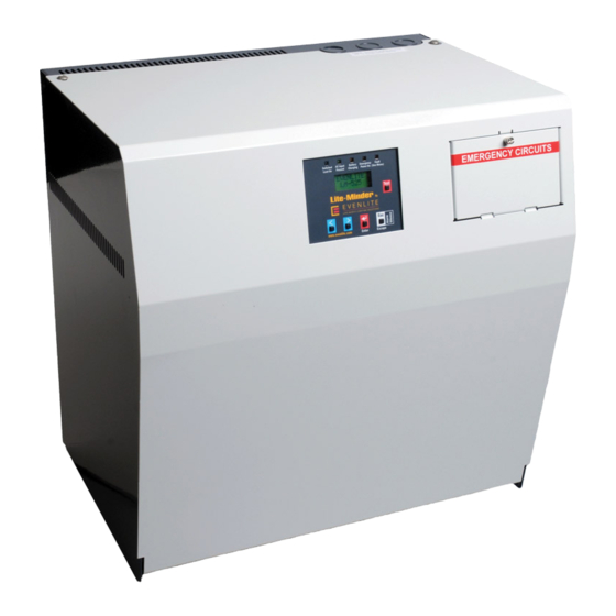
Lite-Minder
By
Installation / Operation Manual - Emergency Lighting
Central Inverter System
IMPORTANT SAFEGUARDS
When using electrical equipment, basic safety precautions should always be followed
including the following:
READ AND FOLLOW ALL SAFETY
INSTRUCTIONS
A. Do not use outdoors
B. Do not mount near gas or electric heaters.
C. Use caution when servicing batteries. Battery acid can cause burns to skin and eyes. If
acid is spilled on skin or in eyes, flush acid with fresh water and contact a physician
immediately.
D. Equipment should be mounted in locations and at heights where it will not readily be
subjected to tampering by unauthorized personnel.
E. The use of accessory equipment not recommended by the manufacturer may cause an
unsafe condition.
F. Do not use this equipment for other than intended use.
This unit contains lethal voltages. There are no user serviceable parts inside. Only authorized
service personnel are to be used for service.
SAVE THESE INSTRUCTIONS
The installation and use of this product must comply with all national, federal, state, municipal
or local codes that apply. Please read this manual thoroughly before installing and operating
the Lite-Minder Central Inverter System.
For assistance please call technical service at 800-967-5573 and speak to a technician
during normal business hours (EST).
EVENLITE - Life Safety Lighting Solutions - 2575 Metropolitan Dr, Trevose, PA 19052 -
www.evenlite.com
Pg. 1
Advertisement
Table of Contents

Related Manuals for Evenlite Lite-Minder


Summary of Contents for Evenlite Lite-Minder
- Page 1 Lite-Minder Central Inverter System. For assistance please call technical service at 800-967-5573 and speak to a technician during normal business hours (EST). EVENLITE - Life Safety Lighting Solutions - 2575 Metropolitan Dr, Trevose, PA 19052 - www.evenlite.com Pg. 1...
-
Page 2: Table Of Contents
Table of Contents Page Introduction Mechanical Design Features Electrical Design Features Receiving and Storage Inspection Storage Installation Location Operating Environment Ventilation Mounting Guidelines 3.4.1 Clearance 3.4.2 Wall Mounting Hole Locations 3.4.3 Knockout Locations AC Connections Removing the Top Cover Removing the AC Breaker/Terminal Block Cover Installing the Input Wires Installing the Output Wires Battery and DC Connections... -
Page 3: Introduction
Pure Sine wave power output intended for use in Emergency Lighting. The Lite-Minder is very efficient. It typically has a steady state loss of just 2 percent of full load while online which makes it ideal for energy saving and green initiatives. It is designed specifically for emergency lighting from the ground up and meets the needs of all lighting loads since it is a pure sine wave output. -
Page 4: Receiving And Storage
2.0 Receiving and Storage Inspection The Lite-Minder Central Inverter and batteries are shipped separately. Upon arrival, please inspect the contents to ensure that no shipping damage has occurred. This is especially important with the batteries to ensure that there are no cracks or leaks. If any damage has occurred, notify the shipping carrier immediately and submit a damage claim. -
Page 5: Installation
3.4.1 Clearance Lite-Minder is convection cooled and air ventilation is through the sides and up the top. Leave at least 4 inches of clearance on the sides and top for proper air circulation. WARNING - Never leave any objects lying on the top of the unit which would prevent proper air flow. -
Page 6: Wall Mounting Hole Locations
3.4.2 Wall Mounting Hole Location Mounting holes are provided for Wall Mount purposes. The location of these holes are at the back side of the cabinet and will accommodate ¼’mounting hardware. Four holes are provided and all 4 should be used when wall mounting. Note: Using the mounting holes provided in the rear of the... - Page 7 Optional Mounting Kit for Wall or Strut Mounting No unit dis-assembly is required Enclosure Outline Mounting Plate Dimensions Inverter hooks on to plate and is Struts secured by 2x 1/4-20 bolts in battery compartment Bracket mounts to enclosure rear panel with 3x 1/4-20 bolts Plate is fastened to wall or struts (hardware supplied by others)
-
Page 8: Knockout Locations
3.4.3 Knockout Locations Electrical Knock Outs are provided on all surfaces of the Lite-Minder. Ensure all metal conduit is secured and tightened creating a good connection to earth ground. Use an Ohm-Meter to check that continuity between conduit and protective earth ground has been established. -
Page 9: Ac Connections
WARNING – Only qualified personnel that are familiar with AC and DC installation techniques and codes (such as an electrician) should perform the installation. WARNING – The Lite-Minder contains lethal AC Voltages. Because of these hazards, always shut down all sources of power before you install, maintain, or service the unit. -
Page 10: Removing The Ac Breaker/Terminal Block Cover
Installing the Input Wires Once the Top Cover and Circuit Breaker Terminal Block Cover are removed: 1. Ensure that the incoming AC voltage to the Lite-Minder is the same voltage rating as the unit. 2. Ensure that the feed breaker from the panel has at least the same breaker rating as the Lite- Minder’s input breaker. - Page 11 WIRE INPUT PORTS CONNECTIONS OPTIONAL SUMMARY ALARM GROUND BAR CONNECTIONS POWER PCB CONNECTIONS OUTPUT CONNECTIONS LINE Note: Up to three output circuit breakers can be mounted on the terminal block rail Standard AC Input/Output Panel Pg. 11...
-
Page 12: Battery And Dc Connections
NOTE –“Wiring from an emergency source or emergency source distribution overcurrent protection to emergency loads shall be kept entirely independent of all other wiring and equipment, unless otherwise permitted” NEC ARTICLE 700 excerpt. Battery and DC Connections WARNING – Only qualified personnel that are familiar with AC and DC installation techniques and codes (such as an electrician) should perform the Installation. -
Page 13: Dc Voltage Of System
Battery 2 (positive) DC Voltage of System The systems DC battery voltage for all models of Lite-Minder is 24 VDC nominal. This voltage is produced by connecting two batteries (each 12 VDC) in series. All required cables are provided by the manufacturer and come pre-installed on the batteries. -
Page 14: Start Up And Shut Down Procedures
Blk (120 V) Org (277V) Wiring 120 / 13.3v Schematic 277v Line J1-2 J6-1 N. On out J1-3 Neutral J6-2 N. Off Out J6-3 Switched Out J1-4 J6-4 Neutral Neutral Neutral Switched Command J1-1 Power PCB Input Signal A250104 Neutral J6-5 Optional Summary Alarm Terminals... -
Page 15: Specifications
Specifications Input Voltage 120 or 277 VAC model dependent Current 5.8A (120V), 2.5A (277V) for 525 Watt Model 4.2A (120V), 1.8A (277V) for 325 Watt Model Frequency 60Hz +/- 2 Hz Protection Input Circuit breaker with fast acting KLK fuse in series a for easy Selective Coordination to upstream feed breaker. -
Page 16: User Interface
Charging Power On (See Menu) display Test Test Lite-Minder Enter Escape Scrolling Display The Root-Menu is a scrolling display that scrolls between Company Name and Model, Operating Mode (System Start Up, Battery Charging or Inverter On), Faults, Output Voltage, Output Current, Battery Voltage, Date and Time, Days, Events and Minutes. -
Page 17: Alarm Menu
Once in the ALARM menu you may see an active alarm present if the heads up LED lamp is illuminated. If no alarms are active, the display will read NO FAULTS. The following alarms are available through the diagnostics within the Lite-Minder inverter. Start Up Faults:... -
Page 18: Event Log
Indicates the day that the event took place. This is a rolling day number so if the event occurred on DAY 0001, it was on the first day the Lite-Minder was started up. LENGTH Indicates how long the Lite-Minder ran on battery power. This is useful to indicate if there was a power outage or just a glitch in AC power. -
Page 19: I-Mon (Off Or On)
PRESS ENTER > TO UPDATE > I-MON VALUE. If the ENTER button is pressed, the connected load current at the output of the Lite-Minder will be stored as the new value. -
Page 20: Battery Charging Mode
There will be two distinct clicks of relays as it goes through the self-check sequence. These relay clicks are the Lite-Minder turning on the output relays to check if any voltages are present and then tickling the output with a small voltage to see if short circuits or overloads are present. -
Page 21: Switched Output
Since the crest factor is very high on the Lite-Minder, loads that have high inrush currents are quickly up and running. This is very beneficial with normally off loads which seem to be more prevalent with modern lighting and green building design techniques. -
Page 22: Warranty
Power mode. 10.0 Warranty There are two separate warranty periods for the Lite-Minder Central Inverter System. The Electronics/Cabinet warranty period is for 3 years from the date of shipment. It is warranted against defects in workmanship and materials under normal and proper use. -
Page 23: Maintenance And Service
Lite-Minder automatically performs monthly tests (every 28 days) and keeps a log of all the events and monthly tests in the event log. Lite-Minder has a self-clearing 28 day counter and resets any time the unit transferred to battery power. If on day 14 the unit had a brief power outage, the counter gets reset and 28 days later (pending no other transfers) a monthly test would be performed. -
Page 24: Battery Replacement
Please dispose of properly by recycling. TIP – Discharging the batteries by letting the Lite-Minder run on Battery Power can be beneficial for several reasons. First, it verifies that the batteries need replacing if it does not make 90 minutes of discharge time.
Need help?
Do you have a question about the Lite-Minder and is the answer not in the manual?
Questions and answers