
Related Manuals for Mitsubishi Electric MELSEC iQ-R RD62P2


Summary of Contents for Mitsubishi Electric MELSEC iQ-R RD62P2
- Page 1 MELSEC iQ-R High-Speed Counter Module User's Manual (Startup) -RD62P2 -RD62P2E -RD62D2...
-
Page 3: Safety Precautions
SAFETY PRECAUTIONS (Read these precautions before using this product.) Before using this product, please read this manual and the relevant manuals carefully and pay full attention to safety to handle the product correctly. The precautions given in this manual are concerned with this product only. For the safety precautions of the programmable controller system, refer to the MELSEC iQ-R Module Configuration Manual. - Page 4 [Design Precautions] WARNING ● Configure safety circuits external to the programmable controller to ensure that the entire system operates safely even when a fault occurs in the external power supply or the programmable controller. Failure to do so may result in an accident due to an incorrect output or malfunction. (1) Emergency stop circuits, protection circuits, and protective interlock circuits for conflicting operations (such as forward/reverse rotations or upper/lower limit positioning) must be configured external to the programmable controller.
- Page 5 [Design Precautions] WARNING ● Especially, when a remote programmable controller is controlled by an external device, immediate action cannot be taken if a problem occurs in the programmable controller due to a communication failure. To prevent this, configure an interlock circuit in the program, and determine corrective actions to be taken between the external device and CPU module in case of a communication failure.
- Page 6 [Security Precautions] WARNING ● To maintain the security (confidentiality, integrity, and availability) of the programmable controller and the system against unauthorized access, denial-of-service (DoS) attacks, computer viruses, and other cyberattacks from external devices via the network, take appropriate measures such as firewalls, virtual private networks (VPNs), and antivirus solutions.
- Page 7 [Wiring Precautions] CAUTION ● Individually ground the FG and LG terminals of the programmable controller with a ground resistance of 100 ohms or less. Failure to do so may result in electric shock or malfunction. ● Use applicable solderless terminals and tighten them within the specified torque range. If any spade solderless terminal is used, it may be disconnected when the terminal screw comes loose, resulting in failure.
- Page 8 [Wiring Precautions] CAUTION ● Ground the shield cable on the encoder side (relay box) with a ground resistance of 100 ohm or less. Failure to do so may cause malfunction. [Startup and Maintenance Precautions] WARNING ● Do not touch any terminal while power is on. Doing so will cause electric shock or malfunction. ●...
- Page 9 [Startup and Maintenance Precautions] CAUTION ● When connecting an external device with a CPU module or intelligent function module to modify data of a running programmable controller, configure an interlock circuit in the program to ensure that the entire system will always operate safely. For other forms of control (such as program modification, parameter change, forced output, or operating status change) of a running programmable controller, read the relevant manuals carefully and ensure that the operation is safe before proceeding.
- Page 10 [Startup and Maintenance Precautions] CAUTION ● Startup and maintenance of a control panel must be performed by qualified maintenance personnel with knowledge of protection against electric shock. Lock the control panel so that only qualified maintenance personnel can operate it. ●...
-
Page 11: Conditions Of Use For The Product
Notwithstanding the above restrictions, Mitsubishi Electric may in its sole discretion, authorize use of the PRODUCT in one or more of the Prohibited Applications, provided that the usage of the PRODUCT is limited only for the specific applications agreed to by Mitsubishi Electric and provided further that no special quality assurance or fail-safe, redundant or other safety features which exceed the general specifications of the PRODUCTs are required. -
Page 12: Introduction
INTRODUCTION Thank you for purchasing the Mitsubishi Electric MELSEC iQ-R series programmable controllers. This manual describes the performance specifications, procedures before operation, wiring, and operation examples of the relevant products listed below. Before using this product, please read this manual and the relevant manuals carefully and develop familiarity with the functions and performance of the MELSEC iQ-R series programmable controller to handle the product correctly. -
Page 13: Compliance With Emc And Low Voltage Directives
COMPLIANCE WITH EMC AND LOW VOLTAGE DIRECTIVES Method of ensuring compliance To ensure that Mitsubishi programmable controllers maintain EMC and Low Voltage Directives when incorporated into other machinery or equipment, certain measures may be necessary. Please refer to one of the following manuals. •... - Page 14 MEMO...
-
Page 15: Table Of Contents
CONTENTS SAFETY PRECAUTIONS ..............1 CONDITIONS OF USE FOR THE PRODUCT . -
Page 16: Relevant Manuals
RELEVANT MANUALS User's manuals relevant to the module Manual name [manual number] Description Available form MELSEC iQ-R High-Speed Counter Module User's Performance specifications, procedures before operation, Print book Manual (Startup) wiring, and operation examples of the high-speed counter e-Manual [SH-081239ENG] (this manual) module MELSEC iQ-R Module Configuration Manual The combination of the MELSEC iQ-R series modules,... -
Page 17: Peripherals
PERIPHERALS The following figure shows the peripherals when the high-speed counter module is used. High-speed counter module Connector... -
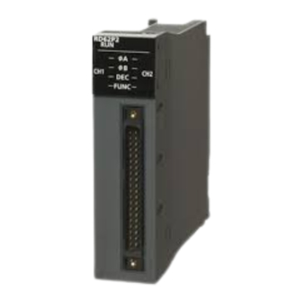
Page 18: Chapter 1 Part Names
PART NAMES This chapter describes the part names of the high-speed counter module. Name Description RUN LED Indicates the operating status. On: In operation Flashing (400ms cycles): Selected as a module for the online module change Off: 5V power supply interrupted or module replacement allowed in the process of the online module change A LED On: Voltage is being applied to the phase A pulse input terminal. - Page 19 MEMO 1 PART NAMES...
-
Page 20: Chapter 2 Specifications
SPECIFICATIONS This chapter describes the performance specifications. Performance Specifications This section describes the performance specifications of the high-speed counter modules. RD62P2 (DC input sink output type), RD62P2E (DC input source output type) Item Specifications Counting speed switch setting 200kpps (100k to 200kpps) 100kpps (10k to 100kpps) 10kpps (10kpps or less) Number of channels... - Page 21 Counting speed switch setting 200kpps 100kpps 10kpps Rise/fall time Both 1 and 2-phase inputs t = 1.25s or less 200kpps 100kpps 10kpps t = 2.5s or less 100kpps 100kpps 10kpps t = 25s or less 10kpps 10kpps t = 500s or less 500pps 2 SPECIFICATIONS 2.1 Performance Specifications...
- Page 22 RD62D2 (differential input sink output type) Item Specifications Counting In multiple of 1 2Mpps 1Mpps 500kpps 200kpps 100kpps 10kpps speed switch (1M to (500k to (200k to (100k to (10k to (10kpps or In multiple of 2 4Mpps setting 2Mpps) 1Mpps) 500kpps) 200kpps)
- Page 23 Minimum count pulse cycle and phase difference The following table lists the minimum count pulse cycle and phase difference for setting each pulse input mode and counting speed. For details on pulse input mode, refer to the following. MELSEC iQ-R High-Speed Counter Module User's Manual (Application) Pulse Waveform (in up count, duty Minimum count pulse cycle, T, and phase difference, t (s), at each counting speed...
-
Page 24: Relation Between The Input Waveform And The Phase Difference Of A Phase Pulse And B Phase Pulse
Relation between the input waveform and the phase difference of A phase pulse and B phase pulse In 2-phase input, inputting pulses of which the phase difference is small between the A phase pulse and B phase pulse can cause an incorrect count. The following figure shows the waveform of a pulse to be inputted to the high-speed counter module, and phase differences between the A phase pulse and B phase pulse in 2-phase input. - Page 25 Phase difference in 2-phase input An input pulse waveform in 2-phase input is subject to both the above condition and the following limit on the phase differences of A phase pulse and B phase pulse: Count Input pulse waveform Up count t1, t2, t3, t4 ≥...
-
Page 26: Chapter 3 Function List
FUNCTION LIST This section describes each counter operation mode and its corresponding functions of the high-speed counter module. For further details on the functions, refer to the following. MELSEC iQ-R High-Speed Counter Module User's Manual (Application) Counter operation mode Available functions in the high-speed counter module differ depending on the counter operation mode used. - Page 27 Function list Counter operation Function Description mode Pulse count mode Linear counter function Counts pulses in the range of -2147483648 (lower limit value) to 2147483647 (upper limit value). If a count exceeds the range, the overflow is detected. Ring counter function Counts pulses repeatedly in the range of CH1 Ring counter lower limit value setting (Un\G20 to Un\G21) to CH1 Ring counter upper limit value setting (Un\G22 to Un\G23), which are set arbitrarily.
-
Page 28: Chapter 4 Procedures Before Operation
PROCEDURES BEFORE OPERATION This chapter describes the procedures before operation. Mounting a module Mount the high-speed counter module in any desired configuration. Wiring Perform wiring of external devices to the high-speed counter module. Page 30 Wiring Adding a module Add the high-speed counter module to a module configuration by using the engineering tool. For details, refer to the following. ... - Page 29 MEMO 4 PROCEDURES BEFORE OPERATION...
-
Page 30: Chapter 5 System Configuration
SYSTEM CONFIGURATION For system configurations using the MELSEC iQ-R series modules, CPU modules that can be used with the D/A converter module, and the number of mountable modules, refer to the following. MELSEC iQ-R Module Configuration Manual 5 SYSTEM CONFIGURATION... - Page 31 MEMO 5 SYSTEM CONFIGURATION...
-
Page 32: Chapter 6 Installation And Wiring
INSTALLATION AND WIRING This chapter describes the installation and wiring of the high-speed counter module. Wiring This section describes the method of wiring an encoder and a controller to the high-speed counter module. Wiring precautions To obtain the maximum performance from the functions of the high-speed counter module and improve the system reliability, an external wiring with high durability against noise is required. - Page 33 Measures against noise • The high-speed counter module may count pulses incorrectly if pulse-like noise is input. • For the input of high-speed pulses, take the following measures against noise: Measure 1: Be sure to use the shielded twisted pair cables. Measure 2: Keep the shielded twisted pair cable at a distance of 150mm or more away from power lines and I/O lines containing much noise, with the cable not being close to them.
-
Page 34: Connectors For External Devices
Connectors for external devices Precautions • Tighten the connector screws within the specified torque range. Screw Tightening torque range Connector screw (M2.6) 0.20 to 0.29Nm • Use copper wire with a temperature rating of 75 or higher for the connector. •... -
Page 35: Interface With External Devices
Interface with external devices The following figure and table show the high-speed counter module interface for connecting external devices. Signal layout and pin numbers of the connector for external devices The following figure shows the signal layout and pin numbers of the connector for external devices 6 INSTALLATION AND WIRING 6.1 Wiring... - Page 36 RD62P2 (DC input sink output type) Internal circuit Signal name Operation Input Operating classification number voltage current (guaranteed (guaranteed CH1 CH2 value) value) Input Phase A pulse 21.6 to 26.4V 2 to 5mA 6.8kΩ input 24V 1/3W 5V or less 0.1mA or less Phase A pulse 10.8 to 13.2V...
- Page 37 RD62P2E (DC input source output type) Internal circuit Signal name Operation Input Operating classification number voltage current (guaranteed (guaranteed CH1 CH2 value) value) Input Phase A pulse 21.6 to 26.4V 2 to 5mA 6.8kΩ input 24V 1/3W 5V or less 0.1mA or less Phase A pulse 10.8 to 13.2V...
- Page 38 RD62D2 (differential input sink output type) Internal circuit Signal name Operation Input Operating classification number voltage current (guaranteed (guaranteed CH1 CH2 value) value) Input Phase A pulse EIA Standard RS-422-A Line receiver 27kΩ input (AM26C32 (manufactured by Texas 1/10W 4.7kΩ 1/10W Instruments Japan Limited.) or equivalent) Phase A pulse...
-
Page 39: Connectable Encoders
Connectable encoders The following lists the encoders that can be connected to the high-speed counter module. Types of the encoder that can be connected to the RD62P2 and RD62P2E • Open collector output type encoder • Voltage output type encoder (Check that the encoder output voltage and output current meet the specifications of the RD62P2 and RD62P2E.) Type of the encoder that can be connected to the RD62D2 •... -
Page 40: Examples Of Wiring Between The High-Speed Counter Module And An Encoder
Examples of Wiring Between the High-Speed Counter Module and an Encoder Example of wiring with an open collector output type encoder (24VDC) RD62P2, RD62P2E Encoder Shielded twisted pair cable 6.8kΩ A20(A13) 3.9kΩ Phase A +24V B20(B13) Shield 330Ω A19(A12) ABCOM B19(B12) Shielded twisted pair cable 6.8kΩ... - Page 41 Example of wiring with a voltage output type encoder (5VDC) RD62P2, RD62P2E Encoder 6.8kΩ A20(A13) Output resistance Phase A 3.9kΩ B20(B13) Shielded twisted pair cable 330Ω A19(A12) Input Input circuit resistance Shield voltage drop ABCOM 2.6 to 3.6V B19(B12) Input resistance 6.8kΩ...
- Page 42 Example of wiring with a line driver (equivalent to AM26LS31) encoder RD62D2 Encoder Shielded twisted pair cable A20(A14) Phase Digital isolator B20(B14) Shield Line receiver Shielded twisted pair cable A19(A13) Phase Digital isolator B19(B13) Shield Line receiver External power supply Alphanumeric characters in the parentheses ( ) indicate the pin number of the channel 2.
-
Page 43: Examples Of Wiring Between A Controller And External Input Terminals
Examples of Wiring Between a Controller and External Input Terminals When the controller (sync load type) has a voltage of 12VDC RD62P2, RD62P2E Controller 1.43kΩ B17(B10) Preset Shielded twisted pair cable 860Ω A16(A09) 450Ω +12V B16(B09) Shield 1.6kΩ CTRLCOM A15(A08) 1.43kΩ... - Page 44 When the controller (source load type) has a voltage of 5VDC RD62P2, RD62P2E Controller 1.43kΩ B17(B10) Preset 860Ω A16(A09) Shielded twisted pair cable 450Ω B16(B09) 1.6kΩ Shield CTRLCOM A15(A08) 1.43kΩ B15(B08) Function start 860Ω A14(A07) Shielded twisted pair cable 450Ω B14(B07) 1.6kΩ...
- Page 45 When the controller is a line driver type RD62D2 1.43kΩ A18(A12) Controller Preset 860Ω B18(B12) 450Ω Shielded twisted pair cable A17(A11) 1.6kΩ PRSTCOM B17(B11) Shield 1.43kΩ A16(A10) Function start 860Ω B16(B10) 450Ω Shielded twisted pair cable A15(A09) 1.6kΩ FUNCCOM B15(B09) Shield Alphanumeric characters in the parentheses ( ) indicate the pin number of the channel 2.
-
Page 46: Examples Of Wiring With External Output Terminals
Examples of Wiring with External Output Terminals When using an EQU terminal (coincidence output), an external power supply of 10.2 to 30VDC is required to drive the internal photocoupler. For the sink output type (RD62P2 and RD62D2) RD62P2, RD62D2 EQU1 Fuse Load A06(A05) - Page 47 MEMO 6 INSTALLATION AND WIRING 6.4 Examples of Wiring with External Output Terminals...
-
Page 48: Chapter 7 Operation Examples
OPERATION EXAMPLES This chapter describes the programming procedure and the basic programs of the high-speed counter module. When applying the program examples provided in this manual to an actual system, properly verify the applicability and reliability of the control on the system. Programming Procedure Take the following steps to create a program for the count operation: Start creating the program. -
Page 49: Program Examples
Program Examples This section shows the system configuration and program examples based on conditions. System configuration X/Y00 X/Y10 X/Y30 · · · X/Y0F X/Y2F X/Y4F (1) Power supply module (R61P) (2) CPU module (R04CPU) (3) High-speed counter module (RD62P2) (4) Input module (RX41C4) (5) Output module (RY41NT2P) Conditions in the program This program is meant to make the high-speed counter module perform the count operation on the following conditions:... - Page 50 Parameter settings Some of the initial setting needs to be set in the parameter settings of the engineering tool. For details on the parameter settings, refer to the following. MELSEC iQ-R High-Speed Counter Module User's Manual (Application) Setting item Description Setting value Pulse input mode...
- Page 51 Mode Label name Program example for PWM output mode Program example for pulse count mode This program example uses the function blocks (FBs) that appear in "Module POU". For details on the function blocks, refer to the following. MELSEC iQ-R High-Speed Counter Module Function Block Reference ■Program example for pulse count mode •...
- Page 52 • Enabling the external coincidence output • Executing a preset ■Program example for the counter function selection • When using the count disable function 7 OPERATION EXAMPLES 7.2 Program Examples...
- Page 53 • When using the latch counter function • When using the sampling counter function 7 OPERATION EXAMPLES 7.2 Program Examples...
- Page 54 • When using the cycle pulse counter function Program example for pulse measurement mode 7 OPERATION EXAMPLES 7.2 Program Examples...
- Page 55 Program example for PWM output mode 7 OPERATION EXAMPLES 7.2 Program Examples...
-
Page 56: Appendix
APPENDIX Appendix 1 External Dimensions This section describes the external dimensions of the high-speed counter module. RD62P2, RD62P2E, RD62D2 27.8 (Unit: mm) APPENDICES Appendix 1 External Dimensions... - Page 57 MEMO APPENDICES Appendix 1 External Dimensions...
-
Page 58: Index
INDEX ..25 Coincidence detection interrupt function ....25 Coincidence output function ... . . 32 Connectors for external devices . - Page 59 MEMO...
-
Page 60: Revisions
Japanese manual number: SH-081238-E This manual confers no industrial property rights of any other kind, nor does it confer any patent licenses. Mitsubishi Electric Corporation cannot be held responsible for any problems involving industrial property rights which may occur as a result of using the contents noted in this manual. -
Page 61: Warranty
WARRANTY Please confirm the following product warranty details before using this product. 1. Gratis Warranty Term and Gratis Warranty Range If any faults or defects (hereinafter "Failure") found to be the responsibility of Mitsubishi occurs during use of the product within the gratis warranty term, the product shall be repaired at no cost via the sales representative or Mitsubishi Service Company. -
Page 62: Trademarks
TRADEMARKS The company names, system names and product names mentioned in this manual are either registered trademarks or trademarks of their respective companies. In some cases, trademark symbols such as ' ' or ' ' are not specified in this manual. SH(NA)-081239ENG-E... - Page 64 SH(NA)-081239ENG-E(2406)MEE MODEL: RD62-U-IN-E MODEL CODE: 13JX05 HEAD OFFICE: TOKYO BLDG., 2-7-3, MARUNOUCHI, CHIYODA-KU, TOKYO 100-8310, JAPAN NAGOYA WORKS: 1-14, YADA-MINAMI 5-CHOME, HIGASHI-KU, NAGOYA 461-8670, JAPAN When exported from Japan, this manual does not require application to the Ministry of Economy, Trade and Industry for service transaction permission. Specifications subject to change without notice.
Need help?
Do you have a question about the MELSEC iQ-R RD62P2 and is the answer not in the manual?
Questions and answers