
Subscribe to Our Youtube Channel
Related Manuals for GGM gastro KDP1064B


Summary of Contents for GGM gastro KDP1064B
- Page 1 OPERATOR'S MANUAL Bakery oven, mini - rotary with electric or gas heating type: WITH INTEGRATED ROTATING TROLLEY WITH OR WITHOUT FERMANTATIPN CHAMBER KDP1064B-KDP1064E-GKDP1064B-GKDP1064E...
-
Page 2: Table Of Contents
Content 1. General functions and description 1.1. Manufacturer information 1.2. Product information 1.3. General view of the equipment 1.4. Product description 1.5. Specifications 1.6. Dimensions (edit) 1.7. General characteristics of the materials used in the product 2. Transport 3. Installing the oven 3.1. -
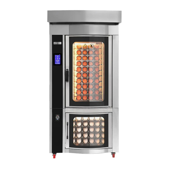
Page 3: General View Of The Equipment
1.3. General view of the equipment KDP1064B... - Page 4 Figure 1.1 Dimensions and elements of the KDP1064E oven. KDP1064E Figure 1.2 Dimensions and elements of the 6040 G 10T oven.
- Page 5 GKDP1064B...
- Page 6 GKDP1064E...
-
Page 7: Product Description
1.4. Product description The oven is only intended for baking food products such as pastries, baked goods, The oven is not intended for baking any other non-food items, unless the manufacturer has specifically agreed to do so! The oven has a baking chamber 1 Fig. 1.1-1.4 (baking chamber), heating and air circulation systems, rack trolley rotation mechanism 4 Fig. -
Page 8: Specifications
1.5. Specifications Type of equipment Rotary oven with Stand Rotary oven with proofing cabinet or Proofing roll-out trolley stand cabinet KDP1064B GKDP1064BÆ KDP1064B KDP1064B Модель Energy carrier Electro Electro Electro о Number of trays 400x600 mm, (pcs) Distance between trays (mm) - Page 9 thickness from 40 to 120 mm. The heat fan has one rotation speed. On the roof of the oven body (Fig. 1.1 - 1.4), a thermal fan, a drive for rotation of a rack trolley, a water pipe of a steam generator, and exhaust ventilation pipes (steam removal) are mounted. The space between these units is insulated with industrial mineral wool slabs.
- Page 10 exhaust duct from the bottom of the oven. This channel serves to discharge excess steam and pressure in the process of vaporization when steam is supplied and the vapor of the batch is released when baking products. Above the second hole there is a pipe with a damper driven by an electromagnet. The damper is closed during baking and opens by pressing a button, and when installing the touch panel, according to the program at the end of baking, to remove baking vapors and smoke from the baking chamber that accumulate in the upper part of the baking chamber.
- Page 12 2. TRANSPORTATION The equipment is delivered to the customer fixed on a pallet, covered with a stretch film or in a crate. Crate packaging is negotiated separately. To move in the factory container, use the methods of movement indicated in "Figure 2". For minor movements of the oven within the premises of its installation site, you can use the wheels, disabling their mechanical fixation.
-
Page 13: Security Measures
3. OVEN INSTALLATION 3.1. Security measures Before switching the oven, check the following: That all safety features are in place; That no part of the oven is damaged; That all foreign objects not related to it are removed from the oven and its immediate vicinity. -
Page 14: Requirements For Premises And Communications
3.2. Oven installation 3.2.1 Requirements for premises and communications The premises in which the oven is installed must be equipped with forced supply and exhaust ventilation and comply with established standards. Calculation of air exchange in the premises is carried out with the help of specialized organizations. - Page 15 3.2.2. Installation, installation and connection of the oven When putting the oven into operation, the first start-up must be carried out after checking electrical connections, the presence of draft in the chimney and the tightness of fuel and gas pipelines. In order to avoid hot air burns when opening the oven door, it is necessary to open the door of the frying chamber in two stages, slightly open the door by 5-10 cm and wait for 20-30 seconds until the heat fan and trolley stop completely, open the...
- Page 16 If the cable is damaged, it must be replaced by a qualified person to avoid danger! - Connect a protective copper conductor with a cross section of at least 10 mm2 to the earthing terminal of the oven, connected to the earthing loop of the bakery. - In the immediate vicinity of the oven, in an easily accessible place on the wall, a switching device (disconnector, automatic switch) of a closed type must be installed, corresponding to the power consumption.
-
Page 17: Preparation For Work
Condensate is drained from the chamber of the pre-proofer by connecting a corrugated drain of the required length. (not included in the scope of delivery) purchased locally. 3.2.3. Preparation for work It is strictly forbidden to work without protective grounding. It is not allowed to operate the oven in the presence of reverse draft (opposite to the direction of natural exhaust ventilation). - Page 18 The initial state of the slide slots is set at the factory. Make adjustments, if necessary, in increments of 1 mm. А В Figure 3.2 Dimensions of gate slots (factory setting) view KDP1064B- KDP1064E-GKDP1064B-GKDP1064E...
-
Page 19: Control Panel
4. CONTROL PANEL 4.1. Oven mechanical control panel TEMPERATURE DISPLAY TIMER DISPLAY SET BUTTON TIME SETTING TEMPERATURES BUTTON SCROLL BUTTON SCROLL BUTTON DOWN ON/OFF BURNER ON/OFF EXHAUST resistance ON/OFF HEAT FAN ON (OPEN) OFF (CLOSE) BAKING CHAMBER FLUTCHES ON/OFF BAKE CHAMBER LIGHT STEAM BUTTON MAIN SWITCH ON/OFF... -
Page 20: Controller Control Panel
conditions are met (the door is open), the heat fan will turn on and the indicator will light up. When the temperature in the baking chamber reaches 500C, the fan will turn off automatically. To resume its operation, close the door. 5.-After the end of the timer (end of baking time), an audible signal will sound, but the baking process will not stop. -
Page 21: Digital Oven Control Panel 4
03 LED Not on this model 04LED Not on this model IP LED Indicates the status of the alarm contact (DI) SN cBeT0,1::i ; i m,r:i: ÜTo6pa)KaeT cqeT BpeMemI B ceKyH,r:i:ax. T emperature setting Used to enter temperature setting mode. button up button Used to start the synchronization operation (Start) and increase the... -
Page 22: Oven Operation
4.3. Mechanical control panel of the pre-proofer Element name Purpose of the element timer Setting the proofing time for dough pieces. (works independently of the heating and steam control scheme) Turn off the signal Turn off the signal for the end of the timer countdown. - Page 23 - Baking can be stopped at any time in the cycle by turning off the oven switch or opening the door. - turn on the exhaust ventilation and cool the oven until the temperature drops below 1000C according to the indicator, or for at least 20 minutes, turn on the heat fan switch to cool the oven. Do not turn off an uncooled oven.
- Page 24 6. ELECTRIC SCHEME Figure 6.1 Album of diagrams of the KDP1064B oven with a gas burner. Designation of elements of the mounting block.
- Page 25 Figure 6.2 Album of diagrams of the KDP1064B oven with a gas burner. Designation of elements of the control panel and controller.
- Page 26 Figure 6.3 Album of diagrams of the KDP1064B oven with a gas burner. Schematic diagram of a power circuit.
- Page 27 Figure 6.4 Album of diagrams of the KDP1064B oven with a gas burner. Electrical circuit diagram of low-voltage circuits.
- Page 28 Figure 6.5 Album of diagrams of the KDP1064B oven with a gas burner. Electrical circuit diagram of low-voltage circuits. Figure 6.6 Album of diagrams of the KDP1064B oven with a gas burner. Designation of electrical circuit elements.
- Page 30 ..� � � •• �I i�il �IJ i�il �1.U � t:,lc:l '° � · t � a::cc i"5 , t-4 !:l.ll 01.lh Figure 6.5 Electrical circuit diagram of the power circuit of the pre-proof e...
- Page 32 7. POSSIBLE FAULTS № П/П Description of the Possible reasons Solutions problem If the burner does not The tightness of the burner is See burner instructions. start broken, gas leakage is possible. Low fuel pressure or no Check the fuel supply to the burner, supply.
- Page 33 The air circulation fan Motor thermal protection Check: voltage, reliability of stator does not turn on. tripped, reset the alarm. contact connections, motor rotation without jamming, performance. The engine has failed. Replace engine. The switch relay is faulty. Check, clean, if necessary replace the switch relay.
- Page 34 Continuous supply of Clogged or defective water Dismantle and clean the valve water to the steam supply solenoid valve elements inside, replace the valve if generator. Evaporator necessary. overflow. Uneven baking of The temperature and baking Adjust the temperature and baking bakery products;...
-
Page 35: Maintenance
8. MAINTENANCE Maintenance of electrical equipment must be carried out by a suitably qualified electrician. Before starting maintenance, stopping for repairs and during sanitization, the power supply must be turned off by the input switch of the power cabinet in compliance with measures to prevent unauthorized supply of voltage. - Page 36 Burner elements and controller. Clean the dust with a vacuum device. At least once Carry out an external inspection of the every 4-6 burner elements. Replace if necessary. months (see burner user manual) Water filters. Check the water filter. 1 Once every 6 months Motor and rack rotation reducer.
- Page 37 9. WARRANTY Guarantees the conformity of the product with the requirements of the current technical documentation and its trouble-free operation during the warranty period, provided that the consumer observes the rules for operation, transportation, storage and installation specified in this instruction manual. The normal operation of the equipment is guaranteed only if the instructions of the operation manual are observed, the Company does not accept claims for the fulfillment of warranty obligations and is not responsible for damage to people and equipment breakdown that occurred due to the following reasons:...
Need help?
Do you have a question about the KDP1064B and is the answer not in the manual?
Questions and answers