Table of Contents
Advertisement
Quick Links
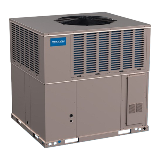
VersaPro™
Gas Package Unit
Installation Manual
MODELS:
• MPG24S060M413B
• MPG30S060M413B
• MPG36S090M413B
• MPG42S090M413B
• MPG48S090M413B
• MPG60S110M413B
Read this manual carefully before installation and keep it where
the operator can easily find it for future reference.
Due to updates and constantly improving performance, the
information and instructions within this manual are subject to
change without notice.
Version Date: 07/16/24
Please visit www.mrcool.com/documentation
to ensure you have the latest version of this manual.
Advertisement
Table of Contents

Subscribe to Our Youtube Channel
Related Manuals for MrCool VersaPro MPG24S060M413B


Summary of Contents for MrCool VersaPro MPG24S060M413B
- Page 1 Due to updates and constantly improving performance, the information and instructions within this manual are subject to change without notice. Version Date: 07/16/24 Please visit www.mrcool.com/documentation to ensure you have the latest version of this manual.
-
Page 2: Table Of Contents
7.1 User Reminders ....................29 7.2 Furnace Section Maintenance ................. 29 7.3 Lubrication ......................31 7.4 Cooling Section Maintenance ................31 7.5 Replacement Parts .................... 32 7.6 Wiring Diagram ....................32 7.7 Charging ......................32 7.8 Blower Motor Speed Taps ................32 mrcool.com... -
Page 3: Safety
Immediately call your gas supplier from a phone outside of the building and follow the gas supplier's instructions. • If you cannot reach your gas supplier, call the fire department. • Do not return to your home until authorized by the gas supplier or fire department. mrcool.com... - Page 4 This appliance contains fiberglass insulation. Respirable particles of fiberglass are known to the state of California to cause cancer. Exhaust gas from this appliance contains chemicals, including carbon monoxide, known to the state of California to cause birth defects of other reproductive harm. mrcool.com...
- Page 5 Improper installation or misapplication of furnace may require excessive servicing or cause premature component failure. Application of this furnace should be indoors with special attention given to vent sizing and material, gas input rate, air temperature rise, unit leveling, and unit sizing. mrcool.com...
- Page 6 Use only with type of gas approved for this unit. Refer to the unit rating plate. • Install this unit only in a location and position as specified in the "Installation" section of these instructions. • Provide adequate combustion and ventilation air to the unit space. mrcool.com...
- Page 7 1. Set the thermostat to its lowest setting. 2. Turn off all electric power to the appliance if service is to be performed. 3. Remove control access panel. 4. Push gas control to "OFF". Do not force. 5. Replace control access panel. mrcool.com...
-
Page 8: Unit Overview
The cooling system of these units is factory-evacuated, charged and performance tested. All units are factory charged with Refrigerant R410A. The figures shown in this manual is for reference only and may be slightly different from the actual product. mrcool.com... -
Page 9: Dimensions
UNIT OVERVIEW 2.4 Dimensions MPG24S060M413B, MPG30S060M413B, MPG36S090M413B, MPG42S090M413B Figure 2.1a- Unit Dimensions *The above figure is for reference purposes only. mrcool.com... - Page 10 UNIT OVERVIEW Figure 2.2b- *The above figures are Dimensions Back and for reference Bottom purposes only. mrcool.com...
- Page 11 UNIT OVERVIEW MPG48S090M413B, MPG60S110M413B Figure 2.3c- *The above figures are Unit Dimensions for reference purposes only. mrcool.com...
- Page 12 UNIT OVERVIEW Figure 2.4d- *The above figures are Dimensions Back & for reference Bottom purposes only. mrcool.com...
- Page 13 UNIT OVERVIEW MPG24S060M413B, MPG30S060M413B, MPG36S090M413B, MPG42S090M413B Figure 2.5a- Component Location *The above figure is for reference purposes only. mrcool.com...
- Page 14 UNIT OVERVIEW MPG48S090M413B, MPG60S110M413B Figure 2.6b- Component Location *The above figure is for reference purposes only. mrcool.com...
-
Page 15: Installation
This unit is designed certified for outdoor installation only. • Installation inside any part of a structure can result in inadequate unit performance as well as property damage. Installation inside can also cause recirculation of flue products into the conditioned space resulting in personal injury or death. mrcool.com... -
Page 16: Attaching Exhaust & Combustion Air Inlet Hoods
1. Remove screws and covers from the supply and return bottom section. 2. Install gasket (factory shipped) around perimeter of cover on the insulate side. 3. Secure covers to the bottom of the unit using existing screws and those supplied in the parts bag. mrcool.com... -
Page 17: Clearance
Right Front Left Table 3.6- Rear Bottom Unit Clearance Duct clearance: 1 inch clearance for all sides of air supply duct. 1. Units must be installed outdoors. Over hanging structure or shrubs should not obscure condenser air discharge outlet. mrcool.com... -
Page 18: Rigging & Handling
Units may be moved or lifted with a forklift. Slotted openings in the base rails are provided for this purpose. CAUTION All panels must be secured in place when the unit is lifted. The condenser coils should be protected from rigging cable damage with plywood or other suitable material. Figure 3.7a- Typical Installations mrcool.com... - Page 19 76 mm (3 in.) below the upper surface of the supporting structure, except that, in a unit designed for use only in a mobile home, the distance shall not be less than 19 mm (3/4 in.). Figure 3.7c- Slab Installation mrcool.com...
-
Page 20: Roof Curb
46-1/16 [1170] 46-1/16 [1170] may be reduced from 1 inch to 1/2 inch between Table 3.8- "E" in.[mm.] 16 [406] 16 [406] combustible roof curb material and this supply air Unit duct. Clearance "F" in.[mm.] 42-3/16 [1070] 30-5/8 [778] mrcool.com... -
Page 21: Ductwork
Do not use a connector which has previously serviced another gas appliance. NOTE The Commonwealth of Massachusetts requires the gas shut-off valve to be a T-handle gas cock. mrcool.com... - Page 22 A backup wrench is required to be used on the valve to avoid damage. The capacity of gas pipe of different diameters and lengths in CFH with pressure drop of 0.5 in. and specific gravity of 0.60 (natural gas) are shown in Table 4.1. mrcool.com...
-
Page 23: Conversion
1-1/2 3307 2299 1858 1559 1417 1275 1181 1086 1023 6221 4331 3465 2992 2646 2394 2205 2047 1921 1811 1606 1496 Example (LP): Input BTU requirement of unit, 150000 Equivalent length of pipe, 60 ft. = 3/4" IPS mrcool.com... -
Page 24: Adjusting Or Checking Furnace Input
For elevations up to 2000 feet, rating plate input rating apply. For high altitudes (elevations over 2000 feet), see conversion kit index for derating and orifice spud sizes. mrcool.com... -
Page 25: Condensate Drain
Table 5-1 using the circuit ampacity found on the unit rating plate. Use the smallest wire size allowable in Table 5-1 from the disconnect to unit. The disconnect must be in sight and readily accessible of the unit. mrcool.com... -
Page 26: Hook-Up
Wiring to be done in the field between the unit and devices not attached to the unit, or between separate devices which are field installed and located, shall conform with the temperature limitation for Type T wire [63°F rise] when installed in accordance with the manufacturer’s instructions. mrcool.com... -
Page 27: Internal Wiring
Transformer is factory wired for 230 volt on 208/230 volt models and must be changed to 208 volt applications. See unit wiring diagram for 208 volt wiring. 5.4 Thermostat The room thermostat must be specifically designed to control package gas electric units. mrcool.com... -
Page 28: Furnace Section Controls & Ignition System
This appliance is equipped with a direct spark intermittent ignition device. This device lights the main burners each time the room thermostat (closes) calls for gas heat. See operating instructions on the back of the furnace/ controls access panel. mrcool.com... -
Page 29: Starting The Furnace
Should overheating occur or the gas supply fail to shut off. Shut off the Manual Gas valve to the appliance before shutting off the electrical supply. Failure to do so can result in an explosion or fire causing property damage, severe personal injury or death. mrcool.com... -
Page 30: Burners
The unit’s furnace should operate for many years without excessive scale build-up in flue passageways; and it should have a qualified installer, service agency, or gas supplier annually inspect the flue passageways, the exhaust system and the burners for continued safe operation, paying particular attention to deterioration from corrosion or other sources. mrcool.com... - Page 31 The manufacturer also recommends that a qualified installer, service agency or the gas supplier clean the flame sensor with steel wool at the beginning of the heating season. WARNING Disconnect main electrical power to the unit before attempting maintenance. Failure to do so may result in electrical shock or severe personal injury or death. mrcool.com...
-
Page 32: Lubrication
If the coil is coated with oil or grease, clean it with a mild detergent-and-water solution. Rinse the coil thoroughly with water. IMPORTANT: Do not use excessive water pressure. Excessive water pressure can bend the tins and tubing of the coil and lead to inadequate unit performance. Be careful not to splash water excessively into unit. mrcool.com... -
Page 33: Replacement Parts
2. Please refer to the Table 10-1 & Table 10-2 and wiring diagram for the proper location of the wire on the speed tap block of the indoor blower motor to obtain the speed you have chosen. 3. After adjusting the wires accordingly,replace control door. mrcool.com... -
Page 34: Operation
As shipped, the circulator blower fan will remain on for 90 seconds after the gas valve closes. When a call for cooling occurs, the circulator fan comes on and remains on for 80 seconds after the call for cooling ends. During normal heating operation, the circulator fan will come on approximately 45 seconds after the gas valve opens. mrcool.com... - Page 35 OPERATION mrcool.com...
-
Page 36: Seer2 Physical Data
1/12 (60W) 1/6 (110W) 1/6 (110W) Nominal Total CFM 2970 2770 2970 Direct Drive Quantity Evaporator Fan Fan Size (in.) 10x10 10x10 10x10 Data Type Centrifugal Centrifugal Centrifugal No. Speeds Motor HP each 1/2 (375W) 1/2 (375W) 1/2 (375W) mrcool.com... - Page 37 1/3 (290W) 1/3 (290W) 1070 1070 Nominal Total CFM 2770 5170 5170 Direct Drive Quantity Evaporator Fan Fan Size (in.) 10x10 11x10-5/8 11x10-5/8 Data Type Centrifugal Centrifugal Centrifugal No. Speeds Motor HP each 3/4 (560W) 3/4 (560W) 3/4 (560W) mrcool.com...
-
Page 38: Airflow Performance
2.60 2.67 (Tap3) Power/W 1281 1240 1190 1142 1092 1045 Middle-3 Current/A 2.82 2.84 2.85 2.96 3.03 3.04 3.13 3.18 (Tap4) Power/W 1280 1244 1194 1140 1083 1032 High Current/A 3.95 4.08 4.07 4.00 4.06 4.03 3.98 (Tap5) Power/W mrcool.com... - Page 39 4.54 4.64 4.74 (Tap4) Power/W 2035 1976 1927 1875 1815 1755 1696 1630 1563 1490 1438 High Current/A 5.66 5.74 5.81 5.85 5.79 5.76 5.73 5.71 5.68 5.66 (Tap5) Power/W * The above airflow data is for reference only. mrcool.com...
-
Page 40: Motor Speed From Factory
An air velocity meter or airflow hood can give a reading of system CFM. • When installation, installer should select the air speed according to the actual setting static pressure. Please • refer to the Table 10.1 & Table 10.2. mrcool.com... -
Page 41: Troubleshooting & Wiring Diagrams
Correct system charge vapor pressure Condenser fan not running Repair or replace (Cooling Mode) Air or non-condensible in system Recover refrigerant, evacuate, and recharge Low head-high Defective compressor valves Replace compressor vapor pressures Incorrect capillary tubes Replace coil assembly mrcool.com... - Page 42 Inspect heat exchanger for blockage. Clean as necessary. Both condenser fan and compressor startup and Abnormal high discharge pressure caused the high Refer to the remedy of "High head-high or normal vapor pressure-cooling shutdown pressure switch act mode". frequently (about three minutes per cycle) mrcool.com...
-
Page 43: High Altitude
3. For furnaces requiring only gas orifice and/or manifold pressure adjustment for installation at high altitude, the furnace installation instructions shall provide adequate details on proper adjustments for various altitudes. 11.3 Fuse Parameters Table 11.3- Fuse Specifications Model Type Rated Voltage Rated Current Dimensions 250Vac 3.15A 5.2x20mm Time Delay 250Vac 3.15A 5x20mm mrcool.com... -
Page 44: Wiring Diagrams
TROUBLESHOOTING & WIRING DIAGRAMS Figure 11a- MPG24 Wiring Diagram mrcool.com... - Page 45 TROUBLESHOOTING & WIRING DIAGRAMS Figure 11b- MPG30 Wiring Diagram mrcool.com...
- Page 46 TROUBLESHOOTING & WIRING DIAGRAMS Figure 11c- MPG36 Wiring Diagram mrcool.com...
- Page 47 TROUBLESHOOTING & WIRING DIAGRAMS Figure 11b- MPG342 Wiring Diagram mrcool.com...
- Page 48 TROUBLESHOOTING & WIRING DIAGRAMS Figure 11b- MPG48 Wiring Diagram mrcool.com...
- Page 49 TROUBLESHOOTING & WIRING DIAGRAMS Figure 11b- MPG60 Wiring Diagram mrcool.com...
- Page 50 VersaPro™ Gas Package Unit Installation Manual The design and specifications of this product and/or manual are subject to change without prior notice. Consult with the sales agency or manufacturer for details.
Need help?
Do you have a question about the VersaPro MPG24S060M413B and is the answer not in the manual?
Questions and answers