Table of Contents
Advertisement
Quick Links
Please read this manual carefully before installation and keep it for future reference.
Installation Manual
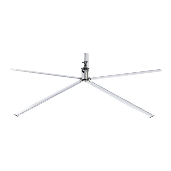
Cool Blade ~ Because We Blow More™
Industrial HVLS Fan
Please keep this manual where the operator can easily find it. Inside, you
will find helpful hints on how to use and maintain your unit properly.
For more info visit www.mrcool.com
Advertisement
Table of Contents

Related Manuals for MrCool HVLS


Summary of Contents for MrCool HVLS
- Page 1 Cool Blade ~ Because We Blow More™ Industrial HVLS Fan Please keep this manual where the operator can easily find it. Inside, you will find helpful hints on how to use and maintain your unit properly. For more info visit www.mrcool.com...
-
Page 2: Table Of Contents
Installation - Fan Blades ..................8 Installation - Arc Plates ................... 9 Installation - Lock Wire Rope ................10 Installation - Sling Wire Rope ................11 Installation - Control Box ..................12 Control Box Summary .................... 13 Fault Codes ........................14 Page 1 mrcool.com... -
Page 3: Safety Precautions
DO NOT keep the control device within children’s reach to avoid accidental operation. CAUTION • MRCOOL will not be responsible for any damage caused by incorrect use or when using not as specified. • MRCOOL will not be responsible for the safety or operation of the automatic systems if alternate parts or configurations are used. -
Page 4: Product Summary
• Minimizes the need for expensive duct work in new construction for both heating and cooling systems • Increases productivity and decreases absenteeism by providing a comfortable workplace environment NOTE Illustrations in this manual are for explanatory purposes only and are not drawn to scale. mrcool.com Page 3... -
Page 5: Installation Preparation
Fan Blade No bad aluminum alloys, Components damaged plastic parts No shipping damage present Control Box Locks & Tiger 1 Set Claw Package 1 Set Compression Package Installing Plate 1 Set Package Set of Screws 1 Set mrcool.com Page 4... - Page 6 CAUTION The following pages in this manual illustrate the HVLS installation procedures. These steps must be followed in sequential order to ensure safe and effective fan operation. A qualified engineer must use the proper tools and equipment necessary to perform the fan installation.
-
Page 7: Installation - Transition Fittings
Examples requiring a separate installation kit include: Z-Purlins, Solid Beam, and Angled I-Beam. • Extensions brackets are available to drop the fan height lower. They are available in 20 inches (500mm), 32 inches (800mm), and 48 inches (1200mm) sizes. mrcool.com Page 6... -
Page 8: Installation - Motor
Motor Components Hex Nuts After installing the transition fitting, attach the motor component to the bottom plate using hex nuts and hexagon screws. Tighten the screws to complete installation. Hexagon Screws Steel Beam Transition Fitting Motor Component mrcool.com Page 7... -
Page 9: Installation - Fan Blades
After installing the transition fittings and motor components, the next step is to install the fan blades. Our HVLS Industrial fan includes aluminum safety plates that connect the blades to the fan chassis forming a safe, stable, and secure design. See the following diagram that illustrates proper fan blade alignment and installation. -
Page 10: Installation - Arc Plates
Bolts, Flat Washers, & Spring Washers Arc Plates Overlap the arc plates, lining up the holes for the bolts. Tighten the bolts to lock the arc plate onto the safety plate. M8 Bolts Plate Aluminum Safety Plate mrcool.com Page 9... -
Page 11: Installation - Lock Wire Rope
See the diagram below that illustrates proper rope placement. Wire Rope Tiger Claw According to the diagram, wind the wire rope through the steel-I-beam, and secure it with the tiger claw to lock it in place. mrcool.com Page 10... -
Page 12: Installation - Sling Wire Rope
Wire Rope Lock Catch 02 Lock Install the wire rope, locks, tiger claws, and lock catches according to the diagram below Tiger C-Shaped Tiger Claw Claw Purlines Wire Rope 02 Lock 02 Lock Lock Catch Lock Catch mrcool.com Page 11... -
Page 13: Installation - Control Box
The control box is used to operate holes as seen in the HVLS fan, change the fan speed, or this illustration change the direction of the fan blades. See the diagrams below and the included Honeywell User Manual for proper installation and wiring procedures. -
Page 14: Control Box Summary
NOTE Please refer to chapter 5 in the Honeywell Control Box User Manual that is included with your fan for detailed Control Box operation instructions. mrcool.com Page 13... -
Page 15: Fault Codes
P-36 Index 3. Note: Following an over current or overload trip (3, 4, 5, 15), the drive may not be reset until the reset time delay has elapsed to prevent damage to the drive. mrcool.com Page 14... - Page 16 Cool Blade ~ Because We Blow More™ Industrial HVLS Fan The design and specifications of this product and/or manual are subject to change without prior notice. Consult with the sales agency or manufacturer for details.
Need help?
Do you have a question about the HVLS and is the answer not in the manual?
Questions and answers