Table of Contents
Advertisement
Quick Links
INSTALLATION MANUAL
(OUTDOOR MMRD7-SS SERIES)
OMNTEC® Mfg., Inc. | 2420 Pond Road | Ronkonkoma | NY 11779 | (631) 981-2001 | Email: OMNTEC@OMNTEC.com | www.OMNTEC.com
PROTEUS
UNIVERSAL REMOTE DISPLAY
OMNTEC® Mfg., Inc. has been certified
1. Open the camera app
2. Focus the camera on
the QR code by gently
tapping the code
3. Follow the instructions
on the screen to view
PDF file
Series
®
Revision 1.3
Document No. DI00007
by DQS Inc. to ISO 9001:2015
Advertisement
Table of Contents

Related Manuals for Omntec PROTEUS Mini-Me


Summary of Contents for Omntec PROTEUS Mini-Me
- Page 1 UNIVERSAL REMOTE DISPLAY Revision 1.3 Document No. DI00007 OMNTEC® Mfg., Inc. has been certified by DQS Inc. to ISO 9001:2015 OMNTEC® Mfg., Inc. | 2420 Pond Road | Ronkonkoma | NY 11779 | (631) 981-2001 | Email: OMNTEC@OMNTEC.com | www.OMNTEC.com...
-
Page 2: Table Of Contents
DIMENSIONS AND EXTERNAL COMPONENTS ..........................8 INTERNAL COMPONENTS ................................9 FRONT PANEL INDICATOR LIGHTS ..............................10 INSTALLATION ....................................10 TERMINAL BLOCK AND POWER SUPPLY WIRING .......................... 11 BOARD CONNECTOR LOCATIONS ..............................12 Document No.: DI00007 www.OMNTEC.com Revision Date: 7-17-2024 Page 2 of 12... -
Page 3: Proprietary Information Notice
LCD display. Avoid direct sunlight exposure when installing. The seller’s sole obligation is to repair or replace parts found to be defective upon evaluation by OMNTEC. Parts can be returned for evaluation by requesting an RMA (Return Material Authorization) from OMNTEC. Any items found to have factory defects after evaluation by OMNTEC through return material authorization process, will be repaired or replaced. -
Page 4: Description
• Do not mount where temperatures are outside of the operating temperature range (see SPECIFICATIONS section) without a heater and/or thermostat. Contact OMNTEC sales for details and options. • Avoid mounting where the display is subject to prolonged periods of direct sunlight. -
Page 5: Specifications
RS-485: 3,000 feet Ethernet: 300 feet (open communication to network devices) Accessories C232-485 RS-232 to RS-485 Converter (Contact OMNTEC sales for more details) C232-422-RD7CTS RS-232 to 422 Booster Kit WRS-232 Wireless RS-232 link; includes both tank gauge and remote transceivers and (2) RD-232C-75 cables... -
Page 6: Preparation
When using an RS-232 connection, the Mini-Me can connect to ATG’s using industry-standard protocol. RS-232/RS-485 OPTION BOARD Refer to document DI00012 (Option Board Installation Instructions) for option bus setup. Document No.: DI00007 www.OMNTEC.com Revision Date: 7-17-2024 Page 6 of 12... -
Page 7: Ethernet Setup
See the programming manual for more information. ADDITIONAL OPTIONS Additional components can plug into Option Bus 1 and 2. Please call OMNTEC for more details. Refer to supplemental document DI00012 (Option Board Installation Instructions). NOTE: Specifications are subject to change without notice. -
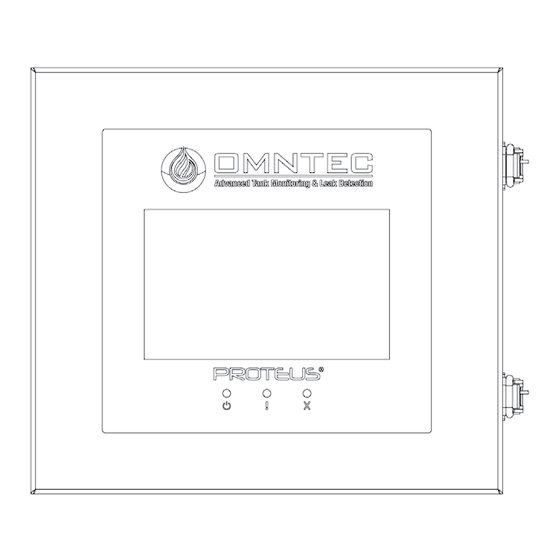
Page 8: Dimensions And External Components
DIMENSIONS AND EXTERNAL COMPONENTS Figure 2.0 Figure 3.0 Figure 4.0 (A) Latches (D) Indicator Lights (B) Mounting Brackets (E) Additional Knockouts (a total of four) (C) Touch-Screen Display (F) Power Supply Knockout Document No.: DI00007 www.OMNTEC.com Revision Date: 7-17-2024 Page 8 of 12... -
Page 9: Internal Components
(H) Grounding Stud (L) Grounding Block (P) RS-232 Connector (I) Reset Button (M) MicroSD USB (Q) Display Cable (J) MCU Cover (N) Ethernet (R) MB-232/485 Option Board (S) Relays Document No.: DI00007 www.OMNTEC.com Revision Date: 7-17-2024 Page 9 of 12... -
Page 10: Front Panel Indicator Lights
4. See TERMINAL BLOCK AND POWER SUPPLY WIRING section for power input details (Figures 7.0). WARNING FAILURE TO COMPLY CAN CREATE AN ELECTRIC SHOCK OR EXPLOSION HAZARD CAUSING DEATH, PERSONAL INJURY, OR PROPERTY DAMAGE. Document No.: DI00007 www.OMNTEC.com Revision Date: 7-17-2024 Page 10 of 12... -
Page 11: Terminal Block And Power Supply Wiring
AVOID TOUCHING OTHER LINES. FAILURE TO COMPLY CAN RESULT IN AN ELECTRIC SHOCK CAUSING DEATH OR PERSONAL INJURY. GROUND (Ground connection must land in terminal block) LINE NEUTRAL Figure 7.0 Document No.: DI00007 www.OMNTEC.com Revision Date: 7-17-2024 Page 11 of 12... -
Page 12: Board Connector Locations
MB-232/485 Option Board (INSTALLED W/ MATING CONNECTOR) (REFERENCE DOC DI00012) Figure 8.0 (M) Micro USB (P) RS-232 (N) Ethernet MB-232/485 CONNECTOR RS-232 PIN-OUTS FROM ATG Figure 10.0 Figure 9.0 Document No.: DI00007 www.OMNTEC.com Revision Date: 7-17-2024 Page 12 of 12...
Need help?
Do you have a question about the PROTEUS Mini-Me and is the answer not in the manual?
Questions and answers