Table of Contents
Advertisement
Quick Links
Advertisement
Table of Contents

Related Manuals for KODERA CASTING C381A


Summary of Contents for KODERA CASTING C381A
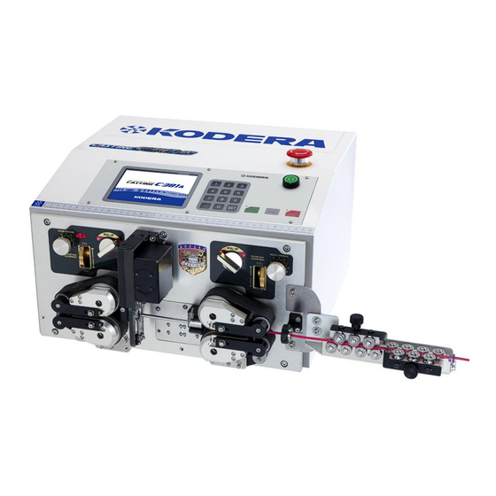
- Page 1 Instruction Manual Ver.10 Please read this instruction manual carefully before using CASTING C381A. Please observe the safety precautions to operate this device safely. Please keep this book at hand so that you can read it whenever necessary.
-
Page 2: Precautions For Use
Safety Precautions If you do not operate the device properly, it may result in failure or accident. Please read this instruction manual carefully before operating this device. ◎In this manual, safety instructions are indicated with “CAUTION” or “WARNING”. Warning: If you do not observe this item properly, it may result in death or severe injury. Caution::... -
Page 3: Precautions For Installation
Caution:Before cleaning, maintenance or inspection, make sure to remove the power cable and check if the device is not energized. It may result in injury or electric shock. Caution:Contact your sales distributer for repair. Improper repair may result in electric shock or fire. Caution :The measure attached to this unit is only for reference. -
Page 4: Table Of Contents
Contents Safety Precautions ・Precautions for Use ....................1 ・Precautions for installation ..................2 1.Name and Motion of the Components on the Front Panel ......... 4 2. Explanation of Components on the Operation Panel ..........4 3.How to Attach and Use CN-03(dressing machine), ............. 5 4. -
Page 5: 1.Name And Motion Of The Components On The Front Panel
1.Name and Motion of the Components on the Front Panel Name of the components ①Left belt feed UP/DOWN Knob ⑧Upper left belt feed unit ②Right belt feed UP/DOWN Knob ⑨Lower left belt feed unit ③Left side roller gap adjusting dial ⑩Lower right belt feed unit ④Right side roller gap adjusting dial ⑪Upper right belt feed unit... -
Page 6: How To Attach And Use Cn-03(Dressing Machine
3.How to Attach and Use CN-03(dressing machine), (optional) Mounting Board for Streightener ・How to mount 1.Remove the screw As of the main unit. 2.Mount the [Mounting board straightener] with provided screw Bs. 3.Mount the Streightener with the provided screw Cs. ・How to use ○... - Page 7 How to connect air tube ・The slug remove air is made to work with the power of the air. Let through the regulator from the compressor to provided coupler to connect to the insertion opening on the rear side of the main body. A suitable numerical value for the air pressure is 0.4~0.5MPa.
-
Page 8: Operation Panel
4.Operation Panel 《Basic》 screen Standard Processing When not selecting ⑤~⑨ on the 《Motion》 screen(P.12). ①《Front Strip Length》:Setting of the stripping length of the front side insulation of the wire. ②《Front Half Strip Length》:Setting of the half stripping length of front side of the wire. Unit: ③《Total Length》:Setting of the cutting length of the wire. - Page 9 ⑪《Current Pieces》:Processed pieces of the wire. During processing, number of the 《 Current Pieces 》 ( processed pieces ) is increasing every second. When you want to clear the displayed number to “0”, press 《Current Pieces》 [0][SET]. ⑫《Batch Pieces》:Number of bundles For example, you can set this when you need 20 bundles of 50pieces totaling 1000 pieces.
-
Page 10: How To Set Up The Processing Conditions
How to set up the processing conditions Wire size 0.3sq Required Pieces 10pieces 1.The wire of the above picture is to be processed. Input ① 《Front Strip Length》 [SET] ② 《Front Half Strip Length》 [SET] ③ 《Total Length》 [7] [0] [SET] ④... - Page 11 Depth of the blade when stripping should be as deep as possible but not damage the core. In case that the blade scratches the core wire, set the numerical value of 《Blade Move Back》 to open the gap of the blade which once cut in by the numerical value of the 《Blade Move Back》 and strip.
- Page 12 5.Setting the wire. A:Keep the “Right belt feed UP/DOWN knob” U(UP) position (Belt feed is up). B:With your hand, insert the wire from the “right side wire guide”,“right side roller”,“guide pipe” to a little bit left from the blade but if it’s too longer, it causes errors.Then down the “upper right belt feed part”.
-
Page 13: Motion》 Screen
《Motion》 Screen From any screen , if 《Motion》 is touched, this screen will be displayed. ①《Motion》:It will light up when the setting is that optional extras are not equipped. ②《Marker》:This key is set when marker which marks on the wire is attached. (See P.20)... - Page 14 ⑩《Rollup 2》: Use this function when an optional left belt feed unit UP/DOWN machine is attached. ⑪《Rollup 1》: Use this function when an optional right belt feed unit UP/DOWN machine is attached. When you select 《Rollup 1》 & 《Rollup 2》, 《...
- Page 15 [Addition] Core diameter in a front and a back end can be established separately. Setting of ≪Core Diameter≫ and ≪Blade Move Back≫ of a ≪Basics≫ screen is usually applied to a Front and a back end likewise, but when You’d like to establish it separately respectively, it's used.
-
Page 16: Basics》 Screen At 《Short Mode
《Basics》 screen at 《Short Mode》 Select 《Short Mode》 on the 《Basics》 screen(P.12). When the length of the remaining wire insulation is shorter than 47.9mm Up the “Left side belt feed part”. When processing short length wire, it is possible to perform half- stripping. -
Page 17: Basics》 Screen At 《Divide Strip
《Basics》 screen at 《Divide Strip》 Select 《Divide Strip》 at 《Motion》 screen (P.12). Divide strip processing, please be sure to enter the Half-strip length. ①《Front Strip Length》:Setting of the stripping length of the front side insulation. ②《Front Half Strip Length》:Setting of the half-stripping length of front side of the wire. - Page 18 《Basics》 screen at 《Double Strip》 Select 《Double Strip》 on the 《Motion》 screen (P.12). ①《Front Strip Length》:Setting of the stripping length of the front side insulation. ②《Front Hal Strip Length》:Setting of the half stripping length of front side of the wire ③Setting of the insulation length of front side which is not stripped.
-
Page 19: Basics》 Screen At Sheath Strip (Half Stripping Of Core Wire)
《Basics》 screen at Sheath Strip (half stripping of core wire) Select ⑧ on the 《Motion》screen (P.12). At above Figure, Semi-Strip scene are displayed so that setting becomes easily understandable. But it is not displayed on the screen of the device. ①《Front Strip Length》:Setting of the stripping length of the front side insulation. -
Page 20: Basics》 Screen At Sheath Strip (Outside Insulation Half Stripping)
⑪Blade’s move back at B when stripping the outside insulation.(See P.10) 《Basics》 screen at Sheath Strip (outside insulation half stripping) Select ⑨ on the 《Motion》 screen (P.12). At above figure, half-stripping scene is displayed so that setting becomes easily understandable. But it is not displayed on the screen of the device. ①《Front Strip Length》:Setting of the stripping length of the front side insulation. -
Page 21: Motion》 Screen At 《Marker
⑩Depth of the blade at B when stripping the outside insulation. (See P.9) ⑪Blade’s move back at B when stripping the outside insulation. (See P.10) 《Motion》 screen at 《Marker》 Select《marker》on the 《Motion》screen (P.12). Set these functions when you use marker. On the above screen, all of the items in marker are displayed to explain. - Page 22 ⑤《Marking Point》:Input the distance from “the V blade of the C381A” to “the center of the marker head”. ⑥《Stamp/Inkjet》:Select the type of the marker to use. ⑦《Specified Number》:When 《Number of Specified》 at ② has been selected, set how many times to mark on a wire at even intervals. ⑧《Print Interval》《Rear Print Point》:...
-
Page 23: Machine Adj》 Screen
Both Ends Bothe Ends Equally-Spaced Equally-Spaced Marking & Marking & Marking & Marking & Simultaneous Asynchronous Simultaneous Asynchronous Marking Marking Marking Marking Front Print Point ○ ○ Output Time ○ ○ ○ ○ Marking Point ○ ○ ○ ○ Specified Number ○... - Page 24 ⑧《Strip Speed》:Setting of the speed of the belt when stripping the insulation. ⑨《Blade Speed》:Setting of blade speed except when cutting wire. ⑩《Cutting Speed》:Setting of the blade speed when cutting wire. ⑪《mm/inch》:Switches the input unit of the machine. mm → inch → mm → ⑫《Step by Step》:Each time when pressing [START]...
-
Page 25: In Case Of Tube Or Cutting Only
5. In case of tube or cutting only Input 《Total Length》 only, and 《Front Strip Length》, 《Front Half Strip Length》, 《Rear Strip Length》 and 《Rear Half Strip Length》 shall be all “0” Any numerical values are acceptable for 《Core Diameter》 and 《Blade Move Back》. Setting of the pieces and gap adjustment are required. -
Page 26: Replacement Of Guide Pipe
8.Replacement of Guide Pipe Knock pin Loosen screw A, and pull it out to the operator’s side. ・Demount Fix the guide pipe so that the knock pin is inserted ・Mount into the knock hole and fasten Screw A. (See Fig.1) Fig. -
Page 27: Maintenance And Inspection
・ Remove Screw C and pull the upper blade out in the Upper Cutter direction of the arrow. (See Fig 5) ・ To mount the blades, fully insert the upper blade into the Guide upper blade holder in the opposite direction of the allow as shown in Fig 5. -
Page 28: Trouble Shooting
12.Trouble Shooting Symptom Where to check How to repair 1)Wire automatically. Rollers don’t rotate. Isn’t it 《Short Mode》? Clear the 《Short Mode》. (See P.15 It starts processing as Isn’t the left belt feed part UP? Make it DOWN. soon as it starts. Isn’t the left side belt gap too narrow? Widen it.(See P.10)... - Page 29 Symptom Where to check How to repair The blade is worn away or Replacement of the blade.(SeeP,24) chipped off? The position of the blade is out Attach the blade again. of alignment?(when replacing the blade) Widen it.(See P,10) 5)Entire the insulation or Isn’t the belt gap narrow?...
-
Page 30: Consumable Supplies List
13.Consumable Supplies List Design & Picture Product Name Order Number Remarks Guide Pipe 2φ 07 - 007 - A0 Guide Pipe 3φ 07 - 007 - B0 Guide Pipe 4φ 07 - 007 - C0 Guide Pipe 5φ 07 -007 - D0 Guide Pipe 6φ... -
Page 31: Guideline To Select The Guide Pipe
14.Guideline to Select the Guide Pipe AVSS Final OD Guide Pipe Final OD Guide Pipe Sq Final OD Guide Pipe 1.8mm 3 φ 2.0mm 3 φ 1.5mm 2 φ 2.2mm 3 φ 0.85 2.2mm 3 φ 1.7mm 2 φ 0.85 2.4mm 3 φ... -
Page 32: Specifications
Specifications Model C381A Outer Dimensions W:430mm × D:420mm × H:270mm Weight 27 kg Power Source AC 100 V ~ 240 V ±10% 50Hz/60Hz Power Consumption 50 W(rating) 300 W(max.) At AC100V Cutting length 0.1mm ~ 99999mm Less than ±(0.1 + 0.0005 ×L)mm L=Cutting length Cutting Tolerance (Depending of the wire)
Need help?
Do you have a question about the CASTING C381A and is the answer not in the manual?
Questions and answers