Table of Contents
Advertisement
Quick Links
Advertisement
Table of Contents

Related Manuals for KODERA CASTING C371A


Summary of Contents for KODERA CASTING C371A
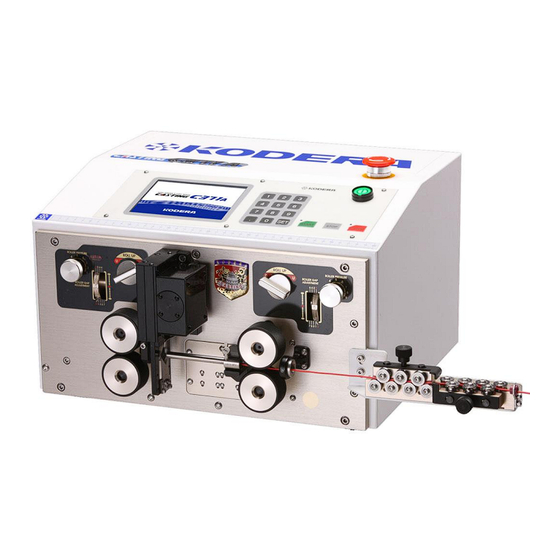
- Page 1 Instruction Manual Ver.14 Please read this instruction manual carefully before using CASTING C371A. Please observe the safety precautions to operate this device safely. Please keep this book at hand so that you can read it whenever necessary.
-
Page 2: Precautions For Use
Safety Precautions If you do not operate the device properly, it may result in failure or accident. Please read this instruction manual carefully before operating this device. ◎In this manual, safety instructions are indicated with “CAUTION” or “WARNING”. WARNING: If you do not observe this item properly, it may result in death or severe injury. CAUTION:... -
Page 3: Precautions For Installation
CAUTION:The measure attached to this unit is only for reference. If you need precise measurement, take its measurement with your measure. CAUTION:Don’t modify this unit. ・Precautions for installation WARNING:Install this unit where it can support the weight and level for sure. If not properly installed, it may cause injury due to the fall down of this device and vibration or operation noise may become loud. -
Page 4: Table Of Contents
Contents Safety Precautions ・Precautions for Use ....................1 ・Precautions for installation ..................2 1.Name and Motion of the Components on the Front Panel ......... 4 2. Explanation of Components on the Operation Panel ..........4 3.How to Attach and Use CN-03(dressing machine), ............. 5 4. -
Page 5: 1.Name And Motion Of The Components On The Front Panel
1.Name and Motion of the Components on the Front Panel Name of the components ①Left side knob for roller UP/DOWN ⑧Upper left roller ②Right side knob for roller UP/DOWN ⑨Lower left roller ③Left side roller gap adjusting dial ⑩Lower right roller ④Right side roller gap adjusting dial ⑪Upper right roller ⑤Sensor signal lamp for wire detection... -
Page 6: How To Attach And Use Cn-03(Dressing Machine
3.How to Attach and Use CN-03(dressing machine), (optional) ・How to attach Attach CN-03 with the cap screws like left figure. ・How to use ○ Push ( plate ) right and left and straightening part is widened. Let the wire ○ through and press Adjust strong and weak of the straightening ○... -
Page 7: Operation Panel
4. Operation Panel 《Basic》 screen Standard Processing When not selecting ⑤~⑨ on the 《Motion》 screen(P.11). ①《Front Strip Length》:Setting of the stripping length of the front side insulation of the wire.(Input range 0.1~999) ②《Front Half Strip Length》:Setting of the half stripping length of front side of the wire. - Page 8 ⑪《Current Pieces》:Processed pieces of the wire. During processing, number of the 《 Current Pieces 》 ( processed pieces ) is increasing every second. When you want to clear the displayed number to “0”, press 《Current Pieces》 [0][SET]. ⑫《Batch Pieces》:Number of bundles For example, you can set this when you need 20 bundles of 50pieces totaling 1000 pieces.
-
Page 9: How To Set Up The Processing Conditions
How to set up the processing conditions Wire size 0.3sq Required Pieces 10pieces 1.The wire of the above picture is to be processed. Input ① 《Front Strip Length》 [SET] ② 《Front Half Strip Length》 [SET] ③ 《Total Length》 [7] [0] [SET] ④... - Page 10 Depth of the blade when stripping should be as deep as possible but not damage the core. In case that the blade scratches the core wire, set the numerical value of 《Blade Move Back》 to open the gap of the blade which once cut in by the numerical value of the 《Blade Move Back》 and strip.
- Page 11 5.Setting the wire. A:Keep the UP/DOWN knob of the right side roller UP position. B:Manually insert the wire from the right side wire guide, right side roller, guide pipe and a bit left side of the blades (too much insertion will be a cause for an error), and put the right side roller down.
-
Page 12: Motion》 Screen
《Motion》 Screen From any screen , if 《Motion》 is touched, this screen will be displayed. ①《Motion》:It will light up when the setting is that optional extras are not equipped. ②《Marker》:This key is set when marker which marks on the wire is attached. (See P.18)... - Page 13 ⑩《Rollup 2》: Use this function when an optional left roller UP/DOWN machine is attached. ⑪《Rollup 1》: Use this function when an optional right roller UP/DOWN machine is attached. When you select 《Rollup 1》 & 《Rollup 2》, 《 Up 》 keys are displayed on the Basics screen.
-
Page 14: Basics》 Screen At 《Short Mode
《Basics》 screen at 《Short Mode》 Select 《Short Mode》 on the 《Basics》 screen(P.11). When the length of the remaining wire insulation is shorter than 47.9mm The left roller should be UP. When processing a short length wire, it is possible to perform half- stripping. -
Page 15: Basics》 Screen At 《Divide Strip
《Basics》 screen at 《Divide Strip》 Select 《Divide Strip》 at 《Motion》 screen (P.11). Divide strip processing, please be sure to enter the Half-strip length. ①《Front Strip Length》:Setting of the stripping length of the front side insulation. ②《Front Half Strip Length》:Setting of the half-stripping length of front side of the wire. -
Page 16: Basics》 Screen At 《Divide Strip
《Basics》 screen at 《Divide Strip》 Select 《Double Strip》 on the 《Motion》 screen (P.11). ①《Front Strip Length》:Setting of the stripping length of the front side insulation. ②《Front Hal Strip Length》:Setting of the half stripping length of front side of the wire ③《Front Disintermidiate Length》:Setting of the insulation length of front side which is not stripped. -
Page 17: Basics》 Screen At 《Sheath Strip》(Half Stripping Of Core Wire)
《Basics》 screen at 《Sheath Strip》(half stripping of core wire) Select ⑧ on the 《Motion》screen (P.11). At above Figure, Semi-Strip scene are displayed so that setting becomes easily understandable. But it is not displayed on the screen of the device. ①《Front Strip Length》:Setting of the stripping length of the front side insulation. -
Page 18: Basics》 Screen At Sheath Strip (Outside Insulation Half Stripping)
《Basics》 screen at Sheath Strip (outside insulation half stripping) Select ⑨ on the 《Motion》 screen (P.11). At above figure, half-stripping scene is displayed so that setting becomes easily understandable. But it is not displayed on the screen of the device. ①《Front Strip Length》:Setting of the stripping length of the front side insulation. -
Page 19: Motion》 Screen At 《Marker
《Motion》 screen at 《Marker》 Select《marker》on the 《Motion》screen (P.11). Set these functions when you use marker. On the above screen, all of the items in marker are displayed to explain. Depending on the setting, items to be displayed change. ①《Both Ends Marking/Equally-Spaced Marking》:Setting how to mark on the wire which is finished. - Page 20 ⑦《Specified Number》:When 《Number of Specified》 at ② has been selected, set how many times to mark on a wire at even intervals. ⑧《Print Interval》《Rear Print Point》: When 《Both Ends Marking》《Separate Marking》 have been selected, 《Rear Print Point》is displayed. When others are selected, display is changed to 《Print Interval》. Rear Print Point:Setting point to print at the rear side.
-
Page 21: Machine Adj》 Screen
《Machine Adj》 Screen From any screen, by touching 《Machine Adj》, it will be displayed. ①Language Selection:Selection of language displayed on the operation panel of C371A. ②《Memory Write》: From “0” to “500” ③《Memory Read》: From “0” to “500” ④《Total Length Correction》:Only the cutting length is corrected. ⑤《Discharge Time》:... - Page 22 [Addition] Core diameter in a front and a back end can be established separately. Setting of ≪Core Diameter≫ and ≪Blade Move Back≫ of a ≪Basics≫ screen is usually applied to a Front and a back end likewise, but when You’d like to establish it separately respectively, it's used.
-
Page 23: In Case Of Tube Or Cutting Only
5. In case of tube or cutting only Input 《Total Length》 only, and 《Front Strip Length》, 《Front Half Strip Length》, 《Rear Strip Length》 and 《Rear Half Strip Length》 shall be all “0” Any numerical values are acceptable for 《Core Diameter》 and 《Blade Move Back》. Setting of the pieces and gap adjustment are required. -
Page 24: Replacement Of Guide Pipe
8.Replacement of Guide Pipe Knock pin Loosen screw A, and pull it out to the operator’s side. ・Demount Fix the guide pipe so that the knock pin is inserted ・Mount into the knock hole and fasten Screw A. (See Fig.1) Fig. -
Page 25: Maintenance And Inspection
・ Remove Screw C and pull the upper blade out in the Upper Cutter direction of the arrow. (See Fig 5) ・ To mount the blades, fully insert the upper blade into the Guide upper blade holder in the opposite direction of the allow as shown in Fig 5. -
Page 26: Trouble Shooting
12.Trouble Shooting Symptom Where to check How to repair 1)Wire automatically. Rollers don’t rotate. Isn’t it 《Short Mode》? Clear the 《Short Mode》. (See P.13 It starts processing as Is the left side roller under the Make it DOWN. soon as it starts. condition of UP?... - Page 27 Symptom Where to check How to repair The blade is worn away or Replacement of the blade.(See chipped off? P,23) The position of the blade is out Attach the blade again. of alignment?(when replacing the blade) 5)Entire the insulation or Widen it.
-
Page 28: Consumable Supplies List
13.Consumable Supplies List Design & Picture Product Name Order Number Remarks Guide Pipe 2φ 07 - 007 - A0 Guide Pipe 3φ 07 - 007 - B0 Guide Pipe 4φ 07 – 007 - C0 Guide Pipe 5φ 07 – 007 - D0 Guide Pipe 6φ... -
Page 29: Guideline To Select The Guide Pipe
14.Guideline to Select the Guide Pipe AVSS Final OD Guide Pipe Final OD Guide Pipe Sq Final OD Guide Pipe 1.8mm 2.5 φ 2.0mm 2.5 φ 1.5mm 2 φ 2.2mm 3 φ 0.85 2.2mm 2.5 φ 1.7mm 2 φ 0.85 2.4mm 3 φ... -
Page 30: Specifications
Specifications Model C371A Outer Dimensions W:430mm × D:420mm × H:270mm Weight 27 kg Power Source AC 100 V ~ 240 V ±10% 50Hz/60Hz Power Consumption 50 W(rating) 300 W(max.) At AC100V Cutting length 0.1mm ~ 99999mm Less than ±(0.1 + 0.0005 ×L)mm L=Cutting length Cutting Tolerance (Depending of the wire)
Need help?
Do you have a question about the CASTING C371A and is the answer not in the manual?
Questions and answers