Table of Contents
Advertisement
Advertisement
Table of Contents
Troubleshooting

Related Manuals for Bausch & Lomb Stellaris Elite BL14455


Summary of Contents for Bausch & Lomb Stellaris Elite BL14455
- Page 1 Operator’s Manual For use with Stellaris Elite™ BL14455 and BL15455...
- Page 2 Preface...
- Page 4 Preface Indications for Use The Bausch + Lomb Stellaris Elite™ vision enhancement system is intended for the emulsification and removal of cataracts, anterior and posterior segment vitrectomy. The system is designed for use in both anterior and posterior segment surgeries. It provides capabilities for phacoemulsification, coaxial and bimanual irrigation/ aspiration, bipolar coagulation, vitrectomy, viscous fluid injection/removal and air/fluid exchange operations.
- Page 5 Preface Reporting of Adverse Reactions Any side effects, adverse events, product complaints, or device malfunctions that may affect safety, should be reported to the manufacturer and competent authority. Contact information can be found on www.bausch.com/contactus. Patents See patents.bausch.com for applicable US patents. Power Outputs COAG 7.5 W, 0.274 A...
- Page 6 Preface Manual Concept Our goal is to provide you with the information you need, with minimal searching. Chapter 1 provides information for a quick setup and answers general questions about the Stellaris Elite™ vision enhancement system. Numerous pictures enhance understanding. Chapter 2 describes the connections to operate the system, including the Graphical User Interface and the Primary (Integrated) Foot Control.
- Page 7 Preface Authorized Representative in Aiming beam Switzerland Aiming beam, blinking Cloud Consult operating instructions for Alternating Current use or consult operating electronic instructions for use Always wear eye protection or face mask when installing or removing the Date of manufacture lamp Aspiration Dispose of Properly...
- Page 8 Preface Ethernet Laser Extrude Laser Emergency Stop Laser Indirect Ophthalmoscope Laser Key Off Fibre-optic handpiece Laser Key On Fluid/Air Exchange Manufacturer Frequency in Hertz Medical device Fuse Fee paid for waste management Importer Microscope Camera Infusion bottle Model number Infusion Cassette Monitor Never touch the silica glass bulb of Irrigation...
- Page 9 Preface Non-sterile Transport Tipping Hazard Symbol Ω ohms See page 1-34 Volt Amps Amperes Phacofragmentation Type BF Applied Part Phone UK Conformity Assessed Prescription only (USA) U/S vitrectomy Primary (Integrated) Foot Control Primary (Integrated) Foot Control ready Viscous Fluid Control Remote interlock connector Vitrectomy Serial number Warning: Hot surface...
- Page 10 Table of Contents...
-
Page 12: Table Of Contents
Table of Contents Table of Contents Getting Started 1.1. Components Shipped with the System ....................1-3 1.2. System Description ..........................1-4 1.2.1 System Console ..........................1-4 1.2.2 Pack Compatibility with Older Systems ..................... 1-6 1.2.3 System Alarm ............................1-6 1.3. Connections and Setup ........................ - Page 13 Table of Contents Detailed Reference 4.1. Advanced Vacuum System Fluidics ....................4-1 4.2. Posterior Functions ..........................4-6 4.3. Anterior Functions ..........................4-43 4.4. Coagulation Function (Posterior & Anterior Modes) ................ 4-62 4.5. Combined Domain ..........................4-67 Cleaning and Sterilization Requirements 5.1.
-
Page 14: Getting Started
1. Getting Started... - Page 16 1. Getting Started Getting Started This chapter is for people who have used this type of ophthalmic vision enhancement system before and want to use the system without reading large portions of the manual. It also provides information on setting up your Stellaris Elite™...
- Page 17 1. Getting Started WARNING: Use of other high-frequency (HF) output equipment in the vicinity of the device or equipment failure could result in an unintended increase in the output power of the bipolar function. WARNING: Grounding reliability can only be achieved when the equipment is connected to an equivalent receptacle marked “Hospital Only”...
-
Page 18: Components Shipped With The System
1. Getting Started technique being performed and the surgeon’s level of proficiency. It is the surgeon’s sole responsibility to use the system settings to achieve optimal operating conditions. Note: If Infusion pressure is elevated an alarm will sound. Go to page 4-35: Fluid Tamponade for further detail. -
Page 19: System Description
1. Getting Started 1.2. System Description 1.2.1 System Console The Stellaris Elite™ vision enhancement system’s modular design enables easy upgrades as technology advances. The system consists of a main housing unit, a user interface screen, surgical modules, a Primary (Integrated) Foot Control, and an infrared remote control (for anterior application only, optional accessory). Handpieces, packs and other accessories are supplied separately. - Page 20 1. Getting Started Figure 1.1. Stellaris Elite™ Posterior/Combined Configuration (with Laser Module) 1. IV Pole. 2. Pneumatic Actuation Port. 3. Posterior Handpiece Connectors. 4. Laser. 5. One-Touch Wheel Locking. 6. User Interface screen. 7. System Switch “On/Off”. 8. Handpiece Connectors. 9. Fluidic Module. 10. System Tray. Your Stellaris Elite™...
-
Page 21: Pack Compatibility With Older Systems
1. Getting Started The computer system includes both audio and visual capabilities, which provide warning messages, alarms, and other audio indications, as well as allowing you to view setup screens, surgical settings, and video from a microscope camera. The volume is adjustable via the touch screen setting globes on the More Screen A/V tab. Two USB ports on the back of the display allow you to save, load, and transfer your customized settings between systems. -
Page 22: Connections And Setup
1. Getting Started 1.3. Connections and Setup WARNING: When using gravity infusion, the ophthalmic irrigation source shall be at or above the patient’s eye level to avoid patient injury. WARNING: Do not add unapproved accessories that modify the effective IV Pole Height. WARNING: For optimum aspiration and reflux performance, the patient’s eye must be at the same level as the Stellaris Elite™... - Page 23 1. Getting Started Figure 1.2. Lower Rear of System (Stellaris Elite™ PC+L) 1. Fuse Holder. 2. Main Power Switch, disconnects system from mains voltage. 3. Ethernet Port. 4. Secondary (LIO) Foot Control Port. 5. Primary (Integrated) Foot Control Backup Cable Port. 6.
- Page 24 1. Getting Started Note: Turning off the Main Power Switch will disconnect the system from mains. Primary (Integrated) Foot Control The Primary (Integrated) Foot Control shipped with all systems contains a laser firing switch, and can use either wired or wireless communication. The first time the Stellaris Elite™ vision enhancement system is used, you must use the wired connection to establish communication between the Primary (Integrated) Foot Control and the Stellaris Elite™...
- Page 25 1. Getting Started WARNING: For optimum aspiration and reflux performance, the patient’s eye must be at the same level as the Stellaris Elite™ vision enhancement system aspiration port. If this is not possible, use the patient eye level offset feature in the programming screen. To set up the Stellaris Elite™...
-
Page 26: Setting Up Your System
1. Getting Started 1.4. Setting Up Your System WARNING: The use of flammable anaesthetics, flammable disinfectants, aerosol sprays, or oxidizing gases such as nitrous oxide (N O) and oxygen should be avoided unless the gaseous agents are sucked away and the liquid agents are fully dried or evaporated. Ensure the flammable liquids are not pooled beneath the patient drape. - Page 27 1. Getting Started Turning System On Plug the power supply cord into the wall. Connect the compressed air hose to the system. If desired, connect the Ethernet cable to the port at the bottom of the Stellaris Elite™ vision enhancement system, and the other end to the optional DMS system for Video Overlay function.
- Page 28 1. Getting Started Figure 1.5. Back bottom of system. 1. Air hose connection. 2. Main Power Switch. Note: The system requires filtered medical grade air or medical grade nitrogen, at 72.5 psig to 100 psig (500 kPa to 690 kPa or 5.0 bar to 6.9 bar) and a flow rate of 2.25 SCFM (63.7 SLPM). Press the power button on the front of the system, and wait for the screen to come on and the software to load.
- Page 29 1. Getting Started Note: The out-of-factory Wireless System Setup is “Disabled”. Software upgrade will also reset the Wireless System Setup to “Disabled”. See System Setup Instructions on page 1-51 to configure Primary (Integrated) Foot Control to wireless operation. If you are going to use the Primary (Integrated) Foot Control in wireless mode, ensure the Foot Control battery is charged, then hold down any button on the Primary (Integrated) Foot Control until the green ready light comes on, indicating that communication has been initiated.
- Page 30 1. Getting Started Once the software has finished loading, the Select Procedure Screen will appear, unless a default procedure has been set (see page 3-26). Figure 1.7. Select Procedure Screen. A Select Surgeon Screen (as shown in Figure 1.8 on page 1-16) will appear when you select any type of procedure from the Select Procedure Screen.
- Page 31 1. Getting Started Figure 1.8. Select Surgeon Screen. Select Surgeon Touch the name of a surgeon on the list to highlight it, then select Confirm to load the parameters for that surgeon and advance to the Setup Screen. Note: A search function is available to filter the surgeon names list when selecting a surgeon file to load.
- Page 32 1. Getting Started Setup Screen The Setup Screen allows you to set certain procedure parameters, and prepare the system for surgical procedures. The Insert Cassette option will be highlighted when you initially see this screen. If desired, select the specific technique, needle, grade, vitrectomy gauge, extrude gauge, and fragmentation needle (Posterior Domain) for the current procedure.
- Page 33 1. Getting Started Figure 1.10. Posterior Domain Case Menu Screen. 1-18 Operator’s Manual 4135904EN...
- Page 34 1. Getting Started Figure 1.11. Combined Domain Case Menu Screen. Advance to the open pack step by selecting Insert Cassette from the Clock Menu. 4135904EN Operator’s Manual 1-19...
-
Page 35: Starting A New Procedure
1. Getting Started 1.5. Starting a New Procedure The Stellaris Elite™ vision enhancement system is user-friendly, and will highlight whichever step is next in a typical procedure. The steps shown on the display screen will vary slightly depending on which optional features are installed on your machine. - Page 36 1. Getting Started Figure 1.12. Schematic diagram of Sterile Draping. 1. Adhere screen drape on the top of the screen panel. 2. Screen drape. 3. Anterior Remote control drape. 4. Mayo Tray drape. CAUTION: Do not exceed a maximum load of 3 lbs. when system tray is fully extended. 2.
- Page 37 1. Getting Started The system will automatically conduct a vacuum sensor and calibration check. Wait until the progress bar shows successful completion to proceed. If the system does not pass, corrective actions will be suggested. Following the successful cassette check, the screen will automatically advance to the Prime and Tune steps. Adaptive Fluidics is a new fluidics function for phacoemulsification surgery during lens removal and I/A only.
- Page 38 1. Getting Started Note: Ensure tube set connection is secure when connecting to the handpiece and system. Note: Fragmentation uses the same power connection as the ultrasound handpiece. Only one function can be used at a time. Note: If a linear coagulation in setup is enabled or a Primary (Integrated) Foot Control button is programmed for coagulation, begin by plugging in the coagulation cord.
- Page 39 1. Getting Started • Select the Prime/Test Vit button to activate the vacuum on right side aspiration line and test the pneumatic vitrectomy function. The handpiece tip must be submerged in Balanced Salt Solution during this process. After the line has been primed, this button will become Test Vit, which will activate the cutter test without aspiration.
- Page 40 1. Getting Started For Anterior Domain: • Select the Prime and Tune button from the Prime and Tune Screen to initiate priming of the irrigation and left aspiration line, followed by tuning of the ultrasound handpiece and a vacuum test. During this process, the IV bottle will be raised to 100 cm or the system will use a pressure of 73 mmHg if AFI is used.
- Page 41 1. Getting Started Figure 1.14. Prime and Tune Screen. This is an example of a posterior domain screen. 5. Advance to Surgery Phase WARNING: Inadvertent activation of functions that are intended for priming or tuning handpieces while the handpiece is in the eye can create a hazardous situation that could result in patient injury. Once the system has been successfully primed and tuned, it will automatically move to the main surgical screen.
-
Page 42: Using Your System In Surgery
1. Getting Started 1.6. Using Your System in Surgery Default parameters and settings are saved in the surgeon preference file, but can be modified during a procedure using the on-screen controls and surgical settings screens (see page 2-6). Your system will display the appropriate surgical screen for the current surgical mode. The interface is visibly different depending on the current operational mode. - Page 43 1. Getting Started Figure 1.16. Anterior Surgical Screen. 1-28 Operator’s Manual 4135904EN...
-
Page 44: Concluding A Surgical Procedure
1. Getting Started Figure 1.17. Combined Surgical Screen. 1.7. Concluding a Surgical Procedure Select End from the Clock Menu. Confirm that you are ready to end the case and eject the cassette, and you will be reminded to close the clamps on the irrigation tube set. A similar End function is accessible from the Setup Screen. - Page 45 1. Getting Started The system will then advance to the End of Case Screen (shown below), lower the IV Pole, and eject the cassette. Figure 1.18. Anterior End of Case Screen. 1-30 Operator’s Manual 4135904EN...
- Page 46 1. Getting Started Figure 1.19. Posterior End of Case Screen. 4135904EN Operator’s Manual 1-31...
- Page 47 1. Getting Started Figure 1.20. Combined End of Case Screen. Remove the fluidics cassette immediately. Remove all disposables from the system. Select Show Me Steps, then Remove Disposables to see a list of which disposables need to be removed, and animations of how to remove each of them. Selecting End of Case Data will capture the End of Case screen as an image.
-
Page 48: Shutting Down The System
1. Getting Started 1.8. Shutting Down the System CAUTION: Never turn the power switch off or disconnect the power without proper system shutdown. Equipment damage can occur. Although there is no maximum activation (on) time or minimum deactivation (off) time defined for the Stellaris Elite™... -
Page 49: Moving Your System To Another Location
1. Getting Started WARNING: Do not Prime and Tune with the infusion line clamp in the open position and the infusion cannula attached to the eye. Remove the infusion cannula, or clamp off the infusion line clamp near the infusion cannula before priming and tuning the system. 1.10. -
Page 50: System Components
1. Getting Started 12. Always maneuver the unit using the handlebar designed for this purpose. Note: Do not store anything on top of the system. 1.11. System Components The Stellaris Elite™ vision enhancement system has an advanced modular design with independent modules concealed in a uniquely designed exterior housing. - Page 51 1. Getting Started User Interface Screen The User Interface Screen is the way the user communicates with the system. See Chapter 2 for basic user interface controls. Technical specifications can be found in Chapter 8. A typical interface setup screen is shown below. Figure 1.21.
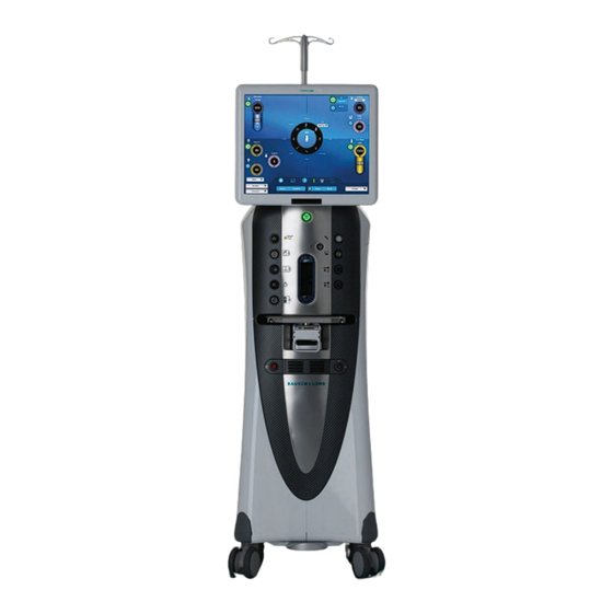
- Page 52 1. Getting Started System Console Figure 1.22. Front of Stellaris Elite™ Posterior/Combined Configuration. 1. IV Pole. 2. Pneumatic Actuation Port. 3. Posterior Handpiece Connectors. 4. Laser. 5. One-Touch Wheel Locking. 6. User Interface screen. 7. System Switch “On/Off”. 8. Handpiece Connectors. 9. Fluidic Module. 10. System Tray. This is the main unit, which contains the connections for all handpieces, Mayo tray, Ethernet connection and system housing.
- Page 53 1. Getting Started For systems left idle more than seven days, the Primary (Integrated) Foot Control must be charged for six hours before use to ensure proper operation. CAUTION: To prevent loss of data, save data before the system shuts down. Figure 1.23.
- Page 54 1. Getting Started • The third port (3 in figure below) is for coagulation (see page 4-64). • The fourth port (4 in figure below) is power for the LIO (available as distributed product, see page 1-76). • The fifth port (5 in figure below) is for Vitesse (see page 4-14). There are five ports down the right side of the system for connecting specific system accessories.
- Page 55 1. Getting Started Ultrasound Functions (Phacoemulsification and Fragmentation) WARNING: Manufacturers of implantable defibrillators recommend that these devices be temporarily disabled when using phacoemulsification systems on patients with these implants. This is especially important when using pulsed phaco modes of operation. Although the implanted devices are designed to reject electromagnetic interference, and Bausch + Lomb vision enhancement equipment is designed to minimize such interference, a chance interaction cannot be ruled out.
- Page 56 1. Getting Started Air Compressor The compressor provides air pressure to drive various pinch valves, Pressurized Infusion (Anterior domain), Air Forced Infusion (Posterior/Combined domains) and Fluid/Air Exchange. It also houses the air pump to drive the Viscous Fluid injection function and the venturi regulator for vacuum control. See Chapter 8 for technical specifications.
- Page 57 1. Getting Started Remote Control (Anterior Domain Only, Optional Accessory) CAUTION: The remote control is not waterproof and is not sterilizable. The remote control must be placed in a sterile cover prior to use in the sterile field. The remote control transmits an infrared signal to a receiver at the bottom of the touch screen. For critical functions you can activate a command directly through the remote control.
-
Page 58: Foot Control
1. Getting Started Note: The batteries should be removed from the remote control if the system is to be idle for more than 30 days. Note: It is your responsibility to dispose of batteries in a safe and environmentally-responsible manner in accordance with local regulations. Digital Media System (DMS) (Optional) The DMS (if available) receives streaming of surgical settings from Stellaris Elite™... - Page 59 1. Getting Started Summary of Wireless Specifications for Wireless Foot Controller Item Specification Bluetooth version V4.0 compliant Operating frequency 2402.0 MHz to 2480.0 MHz (per FCC ID RFRMSR) Operating distances No minimum Ranges 10 meters (maximum) Wireless functions/ Wireless functionality is the same as that in the wired configuration and is configurable capabilities by the user as described in Section 1.12.
- Page 60 1. Getting Started Figure 1.27. Placement of Primary (Integrated) Foot Control During Storage. The Primary (Integrated) Foot Control contains an internal, rechargeable battery. The battery cover has the battery symbol on it. The battery must be charged overnight prior to initial wireless use, or if the system is idle for more than seven days.
- Page 61 1. Getting Started Before installing the replacement battery, check the battery electrical contacts to ensure they are clean and free of contamination. Install the new battery. Press the door toward the compartment and engage door latches to securely close the battery door. Note: Following system shutdown, wait a minimum of 15 seconds before restarting the system.
- Page 62 1. Getting Started Note: The system setup is for enabling wireless functionality; it does not affect the wired functionality. The wired option is always available and active when connected. Note: The system will disable wireless operation once it detects loss of wireless communication at the setup and surgery screens.
- Page 63 1. Getting Started Figure 1.29. Back of Primary (Integrated) Foot Control. 1. Pedal Pitch Tension Adjustment Knob. 2. Backup Power Cord Connection. Figure 1.30. Top of Primary (Integrated) Foot Control. 1. Left Toe Button. 2. Foot Pedal. 3. Right Toe Button. 4. Wireless Indicator. 5. Battery Indicator. 6. Right Heel Button. 7. Laser Firing switch (cover closed) [not functional on the Stellaris Elite™ Anterior systems].
- Page 64 1. Getting Started Figure 1.31. Bottom of Primary (Integrated) Foot Control. 1. Pedal Offset Switch. 2. Battery Compartment Door. 3. Pedal Pitch Tension Adjustment Knob. 4135904EN Operator’s Manual 1-49...
- Page 65 1. Getting Started Figure 1.32. Pedal Offset Switch Indicator (4) and Pedal Offset Positions (5, 6, and 7). 4. Pedal Offset Switch Indicator. 5. Left Offset (for system setup of left foot operation). 6. Center Position (for system setup for left or right foot). 7. Right Offset (for system setup for right foot operation).
- Page 66 1. Getting Started Wireless Primary (Integrated) Foot Control System Setup Note: The out-of-factory Wireless System Setup is “Disabled”. Software upgrade will reset the Wireless System Setup to “Disabled” also. To set up wireless operation, follow steps below: Step 1: Select “Programming” from Setup or “Select Surgeon” screens. Step 2: Select “System Setup”...
- Page 67 1. Getting Started Figure 1.34. System Setup Screen, Foot Control Tab. Step 4: Select Wireless “Enabled” or “Disabled” to configure Primary (Integrated) Foot Control connection mode. Primary (Integrated) Foot Control Status and Wireless Signal Strength Meter Display The status of Primary (Integrated) Foot Control operation is represented by an icon displayed next to the Foot Pedal activation status indicator.
- Page 68 1. Getting Started Display Type Primary Status Action (Integrated) Foot Control Setup Wired (Wireless System NOT detecting Check Primary disabled) wired connection. (Integrated) Foot Possible cause: Control cable Primary (Integrated) connection. Foot Control cable not If Wireless System connected. Setup is on “enabled,” wireless connection will be activated momentarily when...
- Page 69 1. Getting Started Display Type Primary Status Action (Integrated) Foot Control Setup Wireless System detecting No action required. Moderate signal strength. Wireless System detecting Low No action required signal strength. Wireless (System System lost wireless Connect Primary disabled wireless setup) connection signal during (Integrated) Foot procedure.
- Page 70 1. Getting Started health and the environment. For more information about where you can drop off your waste equipment for recycling, please contact your local recycling office or electronic waste hauler. CAUTION: Do not expose the battery to any fluids. The battery, when fully charged, will last for 12 hours.
- Page 71 1. Getting Started • With an extra battery and battery charging cradle, you can connect the wall charger cable to the battery charging cradle. A green light indicates the cradle is on, a second light is yellow when charging is in progress, and green when the battery charging is complete.
- Page 72 1. Getting Started Note: The battery charging cradle MUST be connected to the wall charger to charge the battery. Wireless communication is disabled when the backup cable is in place. The Stellaris Elite™ vision enhancement system will provide a warning message when the battery is nearing the end of its life.
- Page 73 1. Getting Started Color Status Green More than one hour of battery life remains Yellow Battery is charging Red and Blinking Less than one hour of battery life remains Note: The GUI will provide an auditory and visual indication that less than one hour of battery life remains and requires engagement by the user for the condition to be dismissed.
- Page 74 1. Getting Started Single Region Pitch Control (one detent position) The pitch movement is programmed to provide linear control as a function of relative Foot Pedal displacement (e.g., 0° to 15° down corresponds to 0% to 100% output). Examples of single region pitch control are the linear coagulation function and linear vitrectomy function.
- Page 75 1. Getting Started Three Region Pitch Control There are three programmable regions (three detent positions). When programmed for linear control, pitch movement is a function of relative Foot Pedal displacement as shown below. An example is single linear ultrasound phases, where Region 1 is irrigation, Region 2 is fixed aspiration, and Region 3 is linear ultrasound power.
- Page 76 1. Getting Started Dual Linear Setup The outward yaw movement provides linear control of the programmed function, relative to Foot Pedal displacement (e.g., 0° to 15° displacement corresponds to 0% to 100% output). When the Foot Pedal is released, it returns to the center position. Inward yaw movement controls reflux. Yaw Control of Reflux The Foot Pedal may be programmed for use with either the right or left foot.
- Page 77 1. Getting Started Primary (Integrated) Foot Control (BL2295) The laser firing switch is concealed in the heel resting area of the Primary (Integrated) Foot Control (BL2295). To access the laser firing switch, lift the safety cover. The door may be opened to any angle up to 45 degrees. To activate the laser, depress the laser firing switch.
- Page 78 1. Getting Started Center Primary (Integrated) Foot Control Phase Type Dual Linear Region Pitch Yaw Out Control Ultrasound Disabled Irrigation Next submode Fixed aspiration Linear ultrasound Disabled Irrigation Continuous (Continuous Irrigation On Fixed aspiration Irrigation On/Off in all positions Activation in Yaw) Linear ultrasound Continuous Irrigation Off...
- Page 79 1. Getting Started Phase Type Dual Linear Region Pitch Yaw Out Control Irrigation/ Disabled Irrigation Aspiration Linear aspiration Disabled Irrigation Continuous (Continuous Irrigation Irrigation On/Off On in all Activation in Yaw) positions Linear Aspiration Continuous Irrigation Off in R0 and R1 Irrigation Only Disabled Irrigation...
- Page 80 1. Getting Started Phase Type Dual Linear Region Pitch Yaw Out Control Posterior Disabled (Fixed Irrigation On Cutter Vitrectomy Cut) On/Off Linear Aspiration and fixed cut Infusion Auto vitrectomy when On/Off Disabled (Single Irrigation On Single Cut Cut) Linear Aspiration Aspiration on Pitch Irrigation On Linear Cut...
-
Page 81: Illumination Function
1. Getting Started Phase Type Dual Linear Region Pitch Yaw Out Control Viscous Fluid Disable (Fixed Inject (Fixed), Control Inject, Linear Inject (Linear), Inject, Fixed Extract (Fixed) or Extract or Linear Extract (Linear) Extract) Aspiration on Yaw No function or Linear (Dual/Yaw Vac) Irrigation On if... - Page 82 1. Getting Started The Stellaris Elite™ vision enhancement system illumination system comes with a state of the art visualization module to enhance the surgeon’s ability to see effectively during procedures. The output from the illumination probe can attain high-lumen levels if needed; is filtered to minimize hazardous light; and is very flexible, providing easy to access color filter options to enhance safety and tissue visibility.
- Page 83 1. Getting Started Figure 1.44. Irradiance as a function of probe type. Photoretinitis Sensitivity versus wavelength The retina is more easily damaged by ultraviolet and violet-blue light than it is by light with longer wavelengths. The Stellaris Elite™ vision enhancement system incorporates filters to remove ultraviolet light and violet light, but it is not possible to eliminate more of the phototoxic influence without significantly discoloring the light output.
- Page 84 1. Getting Started Time dependency The risk of developing photoretinitis depends not only on the intensity of light, but also on the duration of the exposure, i.e. the total dose of intensity times duration must be limited to prevent damage. This applies to an uninterrupted beam at a particular point on the retina.
- Page 85 1. Getting Started Note: When using two lamps simultaneously at arbitrary settings, the formula for calculating the time to reach the exposure threshold with both lamps running is: tc = 1/[(s1 / t1,100)+(s2 / t2,100)] where: tc = time to reach the threshold for the combination of the two lamps s1 = (setting of Lamp 1 in %/100%) s2 = (setting of Lamp 2 in %/100%) t1,100 = time to reach the threshold with Lamp 1 at 100%...
-
Page 86: Laser Function (Stellaris Elite™ Bl15455 System Only)
1. Getting Started 1.14. Laser Function (Stellaris Elite™ BL15455 system only) Note: Laser functionality may or may not be available in your region. Even if available in your region, it may or may not be installed on your system. Note: Calibration of the laser function should be performed annually, as described on page 6-3. - Page 87 1. Getting Started WARNING: Inspect the moveable microscope filter periodically before use to ensure there are no scratches or other damage, and that it is operating properly. WARNING: Remove all reflective hazards near the laser before operating the laser. WARNING: All support personnel who are present during laser treatment must wear appropriate laser protective eyewear.
- Page 88 1. Getting Started WARNING: There are potential hazards when inserting, sharply bending, or improperly securing the fiber-optic cable. Not following the recommendations of the manufacturer may lead to damage of the fiber or delivery system and/or harm to the patient or user. WARNING: The use of controls or adjustments or performance of procedures other than those specified herein may result in hazardous radiation exposure.
- Page 89 1. Getting Started Laser System Description Photocoagulation in the posterior mode is accomplished with the Stellaris Elite™ (BL15455) vision enhancement system Laser function. The treatment laser provides a visible green (532 nm CW, 2 W max.) class 4 laser for photocoagulation, and a class 2 diode aiming laser (635 nm CW < 1 mW max.). Laser energy is delivered into the eye through a fiber-optic delivery device.
- Page 90 1. Getting Started The laser delivery device connects to top, left port on the front of the system, as shown below. Figure 1.47. Laser handpiece (left) and LIO (right) connected to system. System States The Stellaris Elite™ vision enhancement system laser has four possible states, as described below. Laser System Treatment Laser Aiming Beam...
- Page 91 1. Getting Started An Endo Submode is typically used during vitrectomy, to perform an Endophotocoagulation procedure to seal holes during treatment of retinal detachment, or to perform a panretinal photocoagulation in treatment of diabetic retinopathy. • Laser Indirect Ophthalmoscope (LIO) (optional distributed product) - Single Shot and Pulsed Modes The LIO delivery device adds the treatment option of transpupillary retinal photocoagulation to the diagnostic indirect ophthalmoscope.
- Page 92 1. Getting Started Figure 1.49. Laser mode More Screen showing option to enabled/disabled Laser Mode with laser button door cover. 4135904EN Operator’s Manual 1-77...
- Page 93 1. Getting Started Laser User Interface The Laser Mode can be pre-programmed in the user file to be available in the surgical screen Clock Menu. When Laser Mode is selected, the surgical screen will display laser settings and system status (see Figure 1.50). Figure 1.50.
- Page 94 1. Getting Started Figure 1.51. Laser Submode Option List. The laser function parameters (Power and Duration) can be changed through the setting globes on the right side of the screen. A touch button on the surgical screen, below the laser Interval setting globe, allows toggling between Single Shot and Repeat Modes.
- Page 95 1. Getting Started The status button to the right of counter indicates the current status of the laser: Off, Standby, Ready, Treat. Figure 1.52. Surgical Screen, Laser Endo Submode, Laser in Ready. Aiming Beam The Aiming Beam controls, including the power setting and On/Off control button, are displayed just below and to the left of the center Clock Menu.
- Page 96 1. Getting Started LIO Lamp Tool The LIO Lamp Tool settings are displayed to the left of the Aiming Beam Tool when Laser LIO Submode is selected. The window displays the LIO Lamp status (on/off) and its current power setting. The intensity of the LIO Lamp is displayed as a percentage of power from 5% to 100% in 5% increments.
- Page 97 1. Getting Started Figure 1.54. System with LIO connected. The LIO Lamp cable connects to the port on the left side of the Stellaris Elite™ vision enhancement system, second connector from the bottom. 1-82 Operator’s Manual 4135904EN...
- Page 98 1. Getting Started Figure 1.55. Room Interlock (7) and Microscope Filter Interlock (6) ports. 1. Fuse Holder. 2. Main Power Switch, disconnects system from mains voltage. See 60601-1, paragraph 8.6.7. 3. Ethernet Port. 4. Secondary (LIO) Foot Control Port. 5. Primary (Integrated) Foot Control Backup Cable Port. 6. Microscope Filter Interlock. 7. Room Interlock. 8. Potential Equalization Connector.
- Page 99 1. Getting Started Figure 1.56. Surgical Screen showing Laser LIO selected and Laser in Standby state. The LIO Lamp tool is displayed indicating LIO is connected. EndoProbe WARNING: Avoid unnecessary illumination of the retina using the aiming beam. WARNING: Do not apply excessive stress to the EndoProbe to avoid product damage. WARNING: Avoid contact of the EndoProbe tip with other instruments because of the risk of uncontrolled scatter or damage to the EndoProbe.
- Page 100 1. Getting Started The Laser Endo Submode allows the user to deliver laser energy inside the eye with the laser EndoProbe. Contact your Bausch + Lomb representative for a list of available EndoProbes. Bausch + Lomb offers many EndoProbe configurations to meet user needs, in both straight and curved versions. Illuminating EndoProbes incorporate illumination to provide visualization and laser treatment.
- Page 101 1. Getting Started Endo Submode Setup and Use These procedures assume the system is properly connected and running in the Posterior or Combined domain, and that the system is at the Surgical Screen. Ensure that the room interlock or the room interlock bypass key is connected to the system. Ensure that the eye safety filter is installed in the microscope.
- Page 102 1. Getting Started LIO Submode Setup and Use These procedures assume the system is properly connected and running in the Posterior or Combined domain, and that the system is at the Surgical Screen. Figure 1.59. LIO Headset with Connections. Ensure that the room interlock or the room interlock bypass key is connected to the system. Ensure that the microscope bypass key is connected to the system.
- Page 103 1. Getting Started Press the firing button to activate the laser. Always toggle the laser to the Standby state when not preparing to deliver the laser. When finished, turn the Laser Key one quarter turn counterclockwise to power down the laser. Remove the Laser Key and secure it in a safe location.
- Page 104 1. Getting Started Protection for Ancillary Personnel WARNING: To adequately protect the eyes of ancillary personnel within the Nominal Hazard Zone (NHZ) from both accidental intrabeam (boresight) viewing or long-term viewing of diffuse reflections of the treatment beam, all personnel must wear laser protective eyewear which offer a minimum OD protection of 3.5 or greater at the laser wavelength of 532 nm.
- Page 105 1. Getting Started • Remote Interlock Connector (21 CFR 1040.10 (f)(3)) A connection labeled with the Remote Interlock symbol on the power input module allows incorporation of external interlock switches or safety circuits (for example, a switch that will disable the laser whenever a hospital operating room door opens).
- Page 106 1. Getting Started is electronically interlocked to the module via the SmartKey connector on the power input module to prevent the selection of ready mode when a safety filter is not installed. • Manual Restart (21 CFR 1040.10 (f)(10)) The module can tolerate minor power disruptions lasting only a few cycles without shutting down or changing the intensity of the laser beam.
- Page 107 1. Getting Started Compliance with FDA-Required Laser Safety Features (Summary) • Protective Housing Safety Interlocks (21 CFR 1040.10 (f)(1)) • Safety Interlock (21 CFR 1040.10 (f)(2)) • Remote Interlock Connector (21 CFR 1040.10 (f)(3)) • Key Switch (21 CFR 1040.10 (f)(4)) •...
- Page 108 1. Getting Started Remote Interlock Connector (21 CFR 1040.10 (f)(3)) The Stellaris Elite™ vision enhancement system will not allow the laser to fire unless the Remote Interlock circuit is closed, either through wiring it to a facility interlock circuit or inserting a bypass key. A Remote Interlock connection gives you the opportunity to incorporate your own external interlock switch or safety circuit (for example, a switch that will disable the laser whenever a hospital operating room door opens).
- Page 109 1. Getting Started Description Laser Filters BL3236 Zeiss Fixed ESF BL3240 Zeiss 2 Position Filter ESF BL3245 Moeller Wedel Fixed ESF BL3241 Leica 2 Position Filter ESF BL3247 Leica 4-way Filter BL3237 Leica Fixed ESF BL3239 Laser Filter ESF Mount Topcon BL3242 Adaptor for Fitting of 2 Position Filters Laser Indirect Ophthalmoscopes...
- Page 110 1. Getting Started Description 55.26.27 27 gauge Directional Laser Probe Synergetics Extendable Directional Laser Probes 55.26E 20 gauge Extendable Directional Laser Probe 55.26.23E 23 gauge Extendable Directional Laser Probe 55.26.25E 25 gauge Extendable Directional Laser Probe Synergetics Inverted Directional Laser Probes 55.36.23E 23 gauge Inverted Directional Laser Probe 55.36.25E...
- Page 111 1. Getting Started Description 55.70.23P 23 gauge Flexible Tapered Illuminated Laser Probe 55.70.25P 25 gauge Flexible Tapered Illuminated Laser Probe 55.47.23P 23 gauge Illuminated Directional™ Laser Probe 55.47.25P 25 gauge Illuminated Directional™ Laser Probe 55.48.23P 23 gauge Illuminated Directional™ II Laser Probe 55.48.25P 25 gauge Illuminated Directional™...
-
Page 112: User Interface
2. User Interface... -
Page 114: Basic Interface Controls
2. User Interface User Interface This chapter introduces you to the basic operation of the Stellaris Elite™ vision enhancement system. The Anterior domain system allows the use of phacoemulsification, irrigation/aspiration, irrigation only and coagulation functions. The Posterior domain allows the use of posterior vitrectomy, Fluid/Air Exchange, coagulation, endoillumination, fragmentation, Air Forced Infusion, Viscous Fluid Control (VFC), and laser photocoagulator. - Page 115 2. User Interface Figure 2.2. Setting Tube. Command Button This is a single button control which displays a command, and initiates that action when selected. No value is associated with this control and holding it down performs no additional function. Figure 2.3. Command Button. On/Off Button This is a single round control, which is green when the associated function is on, and grey when it is off.
- Page 116 2. User Interface Toggle Setting Button This is a single button control on a labeled command button, which has a circle that is filled when the function is on, and unfilled when the function is off. Select the button to toggle between the two states. Figure 2.5.
- Page 117 2. User Interface Progress Bar This graphic shows the progress of a procedure. Figure 2.7. Progress Bar. Typewriter Setting Button This is a single button control, which when selected brings up a keyboard, through which you can enter alphanumeric text. Figure 2.8. Typewriter Setting Button. Numeric Keypad Selecting a number on a setting globe brings up the numeric keypad.
- Page 118 2. User Interface Keyboard Sometimes you will need to enter alphabetic or numeric data into the Stellaris Elite™ vision enhancement system. A keyboard similar to that shown below will appear, and you can touch the characters in order to enter them.
-
Page 119: Surgical More Screen
2. User Interface 2.2. Surgical More Screen The More Screen allows easy access to all system parameters. The exact More Screen options available will depend on the current state and system settings. Select the More Screen button (shown below) to open the More Screen. - Page 120 2. User Interface More Screen Vacuum Tab The More Screen Vacuum Tab shows the vacuum settings (minimum and maximum), Primary (Integrated) Foot Control Mapping, vacuum response setting (Global On/Off, response speed), and venting method (Global On/Off, Air or Fluid). Figure 2.13. More Screen Vacuum Tab. More Screen Infusion Tab The More Screen Infusion Tab can show the current Infusion type (Pressurized or IV Pole) and Infusion Units, IV Pole Height (current setting and maximum allowed), Patient Eye Level, Irrigation Shut-Off Delay, Infusion...
- Page 121 2. User Interface Figure 2.14. More Screen Infusion Tab. Note: The Air setting will only be shown on the surgical screen when Pressurized Infusion is selected. Operator’s Manual 4135904EN...
- Page 122 2. User Interface More Screen Ultrasound Tab The More Screen Ultrasound Tab shows the current modulation status (Continuous, Pulsed, Single Burst, Fixed Burst, Multiple Burst) and power level. Depending on which type of ultrasound modulation you are using, you may also see number of pulses per second (PPS), duty cycle (DC), burst duration (BD), pulse interval (PI), waveform type, or waveform depth.
- Page 123 2. User Interface More Screen Visc Tab The More Screen Visc Tab shows the injection or extraction pressure (single value or min and max) and Foot Control Mapping (Linear, Front Loaded, Back Loaded). A surgeon-level setting controls whether units are displayed in psi or kPa (see Chapter 3).
- Page 124 2. User Interface More Screen Coagulation Tab The More Screen Coagulation Tab shows the current minimum and maximum power levels, and the Primary (Integrated) Foot Control Mapping mode. You can adjust either power level setting. Figure 2.17. More Screen Coagulation Tab. 4135904EN Operator’s Manual 2-11...
- Page 125 2. User Interface More Screen Vitrectomy Tab The More Screen Vitrectomy Tab allows you to change the current subphase (Fixed Cut, Co-Linear Vit, Dual/Yaw Vac, Dual/Yaw Cut, Single Cut), the current settings for the minimum and maximum CPM (cuts per minute), and the current Primary (Integrated) Foot Control Mapping (if applicable).
- Page 126 2. User Interface More Screen Foot Control Tab The More Screen Primary Foot Control Tab has three subtabs that allow you to view and edit Settings, Regions, and the Status of the Primary (Integrated) Foot Control. These functions are described in detail in the Primary (Integrated) Foot Control section (see page 1-43).
- Page 127 2. User Interface Figure 2.20. Continuous Irrigation On/Off Activation in Yaw Enabled. 2-14 Operator’s Manual 4135904EN...
- Page 128 2. User Interface Figure 2.21. Continuous Irrigation On/Off Activation in Yaw Disabled. 4135904EN Operator’s Manual 2-15...
- Page 129 2. User Interface Figure 2.22. Disabling Continuous Irrigation On/Off Activation in Yaw in the Single Linear Phaco Phase More Screen Foot Control Tab, Settings Subtab, Allows Ultrasound Modulation on Yaw. 2-16 Operator’s Manual 4135904EN...
- Page 130 2. User Interface The Regions Subtab shows the current settings for right or left footed operation, mode change control, the Foot Pedal pitch regions and detent options. You can modify the starting depression position for each region. Figure 2.23. More Screen Foot Control Tab, Regions Subtab. 4135904EN Operator’s Manual 2-17...
- Page 131 2. User Interface The Status Subtab shows the current status of several Foot Pedal options, including communication status, battery status, and signal strength. These are informational only and not user editable. Figure 2.24. More Screen Primary (Integrated) Foot Control Tab, Status Subtab. 2-18 Operator’s Manual 4135904EN...
- Page 132 2. User Interface More Screen A/V Tab The More Screen A/V Tab and its subtabs allow you to change many aspects of the audio and video display. The Audio Subtab controls the master volume for the system, as well as the specific tone and volume used for Alert, Aspiration, Coagulation, Elevated Infusion, Irrigation Infusion, Key, Laser, Reflux, Occlusion, Timer, Ultrasound, Visc Inject, Vitesse Vitrectomy, and Voice Confirmation.
- Page 133 2. User Interface The Display Tab control allows you to adjust the display brightness, voice confirmation language, and to clear the average values and elapsed times for the surgical functions for this case. Figure 2.26. More Screen A/V Tab, Display Subtab. 2-20 Operator’s Manual 4135904EN...
- Page 134 2. User Interface The Video Overlay Subtab allows you to select the language to be used for video overlays. You can also set whether or not the system will display or combine the Video Overlay Format U/S Averages, or whether or not the system will combine settings information. By default, the U/S data is shown as three separate lines on the video overlay.
- Page 135 2. User Interface More Screen Illuminator Tab The More Screen Illuminator Tab allows you to enable or disable the upper and lower lamps and to set the current power and filter (none, amber, green tint, yellow tint). The bottom section of the More Screen Illuminator Tab displays the type of bulb currently installed in each lamp and the number of hours of lamp life remaining.
- Page 136 2. User Interface More Screen Laser Tab The More Screen Laser Tab includes the Laser Power (mW), Laser Duration (ms), Aiming Beam in Standby (On/Off), Aiming Beam Intensity (%), Foot Pedal (Integrated Foot Pedal, Secondary Foot Pedal), Default Laser Shot (Single, Repeat), Aiming Beam During Pulse (On/Off), LIO (On/Off, %), and Laser Foot Control Buttons (Enabled, Disabled).
- Page 137 2. User Interface More Screen Vitesse Tab The More Screen Vitesse Tab includes settings for Vitesse modulation, submode, power (minimum and maximum for linear mapping and maximum only for fixed), and foot control mapping. Figure 2.30. More Screen Vitesse Tab. 2-24 Operator’s Manual 4135904EN...
- Page 138 2. User Interface More Screen Messages Tab The More Screen Messages Tab lists all system messages. You can scroll through the messages to see any issues that have arisen during the current case. Figure 2.31. More Screen Messages Tab. 4135904EN Operator’s Manual 2-25...
-
Page 139: Surgical Screen Layout
2. User Interface 2.3. Surgical Screen Layout The surgical screen is divided into four quadrants: the center of the screen displays the clock menu for procedure selection and navigation, and different settings and functional controls are displayed in the surrounding quadrants. The upper left corner displays the vacuum setting. The upper right corner displays the IV Pole Height setting, air pressure setting, irrigation function status, fill function for the surgical beaker, and Adaptive Fluidics status. - Page 140 2. User Interface Clock Menu The round Clock Menu in the middle of the screen can display up to 12 phases or exceptions. The exceptions usually appear on the left side of the Clock Menu, against a darker background. These are user-defined to be any mode or phase type.
- Page 141 2. User Interface If the Pressurized Infusion function is programmed in the surgeon file, the upper right corner of the screen displays the current setting of air pressure when the pump is not running. When the pump is switched on, the same area will display the actual output pressure.
- Page 142 2. User Interface Figure 2.34. Surgical Screen. The Surgical Screen user controls provide the capability to adjust the Vacuum settings from 0 mmHg to 660 mmHg, similar to the controls for the pneumatic vitrectomy cutter. The user controls also provide the capability to control cutting power expressed as a percent of the maximum power. Coagulation (Fixed) If one of the Primary (Integrated) Foot Control Buttons has been programmed to control coagulation, a small Coagulation setting globe will appear, showing the current maximum fixed setting for the coagulation function.
- Page 143 2. User Interface Status Bars At the bottom of the screen, the status section displays the current value of a number of system parameters. The top section includes a cassette ejection button, fluid collection device fill level indicator, the More Screen button, as well as the Primary (Integrated) Foot Control battery level, Foot Control icon, and wireless signal strength indicators (see page 1-52).
- Page 144 2. User Interface To enable the Adaptive Fluidics function from the surgical More Screen: Select More Screen button as shown in Figure 2.37. Select the Infusion Tab on the pop-up screen to display infusion options. Set Infusion Type to Pressurized, as shown in Figure 2.38. Set Adaptive Fluidics to Enabled, as shown in Figure 2.38.
- Page 145 2. User Interface Figure 2.39. Anterior Surgical Screen with More Screen Button to Turn Adaptive Fluidics Function On/Off. 2-32 Operator’s Manual 4135904EN...
- Page 146 2. User Interface Figure 2.40. Combined Surgical Screen with More Screen Button to Turn Adaptive Fluidics Function On/Off. 4135904EN Operator’s Manual 2-33...
- Page 147 2. User Interface Figure 2.41. Adaptive Fluidics Turned On. Figure 2.42. Adaptive Fluidics Turned Off (Pressurized Infusion Remains On). 2-34 Operator’s Manual 4135904EN...
-
Page 148: Customizing Your System
3. Customizing Your System... - Page 150 3. Customizing Your System Customizing Your System This chapter explains how to customize your Stellaris Elite™ vision enhancement system to achieve maximum flexibility for your operating needs. Note: Surgical devices may not be operated during programming. Each surgeon using the Stellaris Elite™ vision enhancement system can program the system to their own preferred operating configuration and instrument parameters.
- Page 151 3. Customizing Your System Figure 3.1. Programming Screen Layout. To program system parameters, select Programming from main Clock Menu on the Surgeon Level Programming Screen or the Setup Surgical Screen. Operator’s Manual 4135904EN...
- Page 152 3. Customizing Your System The Main Programming Screen will appear, from which you can perform the following functions: • Surgeon Settings • System Setup • System Configuration • System Calendar • Remote Service Figure 3.2. Main Programming Screen. Each of these functions is described in more detail below. At any time, you can select Programming to return to the Main Programming Screen, or Exit Programming to return to the Surgeon Level Programming Screen or the Setup Surgical Screen.
-
Page 153: Manage Settings
3. Customizing Your System 3.1. Manage Settings Select Surgeon Settings from the Main Programming Screen, and a new screen will appear through which you can customize an existing surgeon’s file, create a new surgeon preference file by copying from an existing one, back up files, restore files from a backup, or delete surgeon preference files. - Page 154 3. Customizing Your System Customize a Settings File To change the settings for a currently existing preference file, select Surgeon Settings on the Main Programming Screen. A list of all surgeon preference files currently loaded on your Stellaris Elite™ vision enhancement system will appear.
- Page 155 3. Customizing Your System Customize Profile To change the surgeon’s name associated with a settings file, the default screen language, Viscous Fluid Injection Units (PSI, kPascal), enable or disable use of the remote control, or the surgeon password, select the Profile Tab on the Surgeon Level Programming Screen.
- Page 156 3. Customizing Your System Customize Technique To change the techniques available for a particular surgeon or modify their settings, select the Technique Tab on the Surgeon Level Programming Screen, and a list of currently defined techniques will appear. You can select any technique from the current list and use the Move Up and Move Down buttons to rearrange the order in which they appear.
- Page 157 3. Customizing Your System Figure 3.7. Customize Technique Screen. • Profile Tab—Technique Name, Remote Control (Enable, Disable) • Phases Tab—Each technique may include up to eight phases. The Phases Tab shows the name of the phase, and the mode for that phase. Phases can be added, deleted, or re-ordered. They may also be customized, as described below.
- Page 158 3. Customizing Your System For combined techniques, Infusion Type, Infusion Units, F/AX pressure, Infusion pressure, Elevated Infusion pressure, and Elevated F/AX pressure settings are displayed. They are not displayed in anterior modes. For anterior techniques, the IV Pole Height setting and Pressurized Infusion pressure setting are displayed. Customizing Phases and Exceptions Both Phases and Exceptions can be re-ordered and customized.
- Page 159 3. Customizing Your System Figure 3.8. Customize Phase Screen. Select Customize, and more options specific to that function will appear, and can be modified. These can include Profile, Primary (Integrated) Foot Control, Vacuum, Infusion, U/S Setting, U/S Waveform, Cut, Coagulation and Visc tab. Which tabs are displayed depends on which mode you are in, and whether Customize Settings by Case is disabled or enabled, as detailed in the table below.
-
Page 160: Surgeon Level Settings
3. Customizing Your System Mode Tabs Displayed on Phase Programming Screens Irrigation Profile, Primary (Integrated) Foot Control, Infusion Viscous Fluid Control Profile, Primary (Integrated) Foot Control, Visc Viscous Fluid Control (Dual/Yaw Vac submode) Profile, Primary (Integrated) Foot Control, Visc, Vacuum and Infusion Extrude Profile, Primary (Integrated) Foot Control, Vacuum, Coag (if Coag on Yaw is enabled), Infusion... - Page 161 3. Customizing Your System When Anterior Modes is selected, the Foot Pedal region 1, 2 and 3 start positions are adjustable. The anterior mode start positions are used in the anterior domain and the anterior modes of the combined domain. Figure 3.9. Customize Primary (Integrated) Foot Control Screen. 3-12 Operator’s Manual 4135904EN...
- Page 162 3. Customizing Your System Customize Fluidics To set the parameters for Fluidics functions, select the Fluidics Tab on the Surgeon Level Programming Screen. You can set the following options by selecting the current setting, and then selecting the new setting from the menu.
- Page 163 3. Customizing Your System Customize A/V (Audio/Visual) To set the parameters for audio and visual functions, select the A/V Tab from the Surgeon Level Programming Screen. You can adjust both Display Brightness and Master Volume by using the setting globes on this screen. To change the tone or volume of a tone that is sounded for a particular condition, select the function from the list at the bottom of the screen, and that condition will appear in the change section in the middle of the screen.
- Page 164 3. Customizing Your System Figure 3.11. Customize A/V Settings Screen. 4135904EN Operator’s Manual 3-15...
- Page 165 3. Customizing Your System Customize Video Overlay To set the parameters for the DMS Video Overlay functions, select the Video Overlay Tab on the Surgeon Level Programming Screen. Through this tab you can set whether or not the system will combine Video Overlay Format information (U/S Averages, settings).
-
Page 166: Manage Surgeon Files
3. Customizing Your System 3.3. Manage Surgeon Files Create a New Settings File The system will come pre-loaded with several system files, including System Settings, System Vitesse, and System VFM1. To create a new surgeon preference file, select the Create Tab from the Surgeon Settings Screen, then select the existing surgeon file which has settings most similar to the file you are going to create. - Page 167 3. Customizing Your System Once all the desired techniques are highlighted, select Confirm and a keyboard will appear, through which you can enter the name for the new surgeon file, then select Enter. The name of the new file will appear on the left side of the screen, and a new set of tabs (Profile, Technique, Primary (Integrated) Foot Control, and Fluidics) will appear across the top of the screen.
- Page 168 3. Customizing Your System Figure 3.14. Backup Settings File Screen. 4135904EN Operator’s Manual 3-19...
- Page 169 3. Customizing Your System Restore a Settings File To restore an existing surgeon preference file from a USB memory device, select the Restore Tab from the Manage Settings Screen, then insert the device into one of the two USB ports on the back of the system console, behind the round sliding door.
- Page 170 3. Customizing Your System Delete a Settings File To delete an existing surgeon preference file, select the Delete Tab from the Manage Settings Screen, select the file or files to be deleted, and select Confirm. Figure 3.16. Delete Settings File Screen. 4135904EN Operator’s Manual 3-21...
-
Page 171: System Setup
3. Customizing Your System 3.4. System Setup Select System Setup from the Main Programming Screen, and a new screen will appear through which you can set the Date/Time for the system, view the System IDs, and set operating room parameters. Any changes you make here are implemented immediately. - Page 172 3. Customizing Your System System ID To monitor or change the identifying names of your Stellaris Elite™ vision enhancement system, select the System ID Tab at the top of the System Setup Screen. You can enter or update the account name and system name that have been assigned to your Stellaris Elite™...
- Page 173 3. Customizing Your System Rooms To assign names to the operating rooms in which your Stellaris Elite™ vision enhancement system is used, select the Rooms Tab at the top of the System Setup Screen, select any room button, and the keyboard will appear, where you can enter the name for that room.
- Page 174 3. Customizing Your System Primary (Integrated) Foot Control To change the way your Stellaris Elite™ vision enhancement system connects to the Primary (Integrated) Foot Control, select the Primary (Integrated) Foot Control Tab at the top of the System Setup Screen. Select Enabled or Disabled to configure the connection mode.
-
Page 175: System Configuration
3. Customizing Your System 3.5. System Configuration To see a detailed listing of the software and hardware configurations of your system, select System Configuration from the Main Programming Screen. Figure 3.21. System Configuration Screen. 3.6. System Calendar To set up your system to default to certain surgeon preference files and room numbers at certain times of the week, select System Calendar from the Main Programming Screen, and the System Calendar Screen will appear with three or four user-editable columns. - Page 176 3. Customizing Your System Figure 3.22. System Calendar Screen. The second column, next to the listing of the days of the week, determines if the default surgeon applies to the full day, or if separate defaults will be applied to the morning and afternoon of that weekday. Select toggle between full day or morning and afternoon settings.
-
Page 177: Customization
3. Customizing Your System 3.7. Customization The following tables detail which options can be customized at which level. Audio and Visual Customization Settings Parameter Options/Ranges/Step Sizes Level Surgeon name Typewriter data entry (32 characters max) Surgeon Screen/Voice language English (U.S.), English (U.K.), Français, Deutsch, Italiano, Surgeon Español, Português, Nederlands, Norsk, Svenska, Česky, Dansk, ελληνικά, Suomi, Magyar, 日本語, Polski,... - Page 178 3. Customizing Your System Parameter Options/Ranges/Step Sizes Level Video overlay display format Ultrasound averages lines - Display, Display Combine, Surgeon No Display Combine settings lines - No, Yes Video overlay overscan 0% to 5%, by 1% Surgeon allowance Remote control Disabled and Enabled Surgeon Technique name Typewriter data entry...
- Page 179 3. Customizing Your System Foot Control Parameter Options/Ranges/Sizes Level Operation Right Foot, Left Foot Surgeon Mode change Not While Active, Allow-Limit Pedal, Allow-Remap Pedal, and Surgeon control Allow-No Limiting Detents Disabled, Enabled (R1/R2/R3), Enabled (R2/R3) Surgeon Starting position Region 1: 2% to 5%<R2 start, by 5% Surgeon Region 2: 5%>R1 start to 5%<R3 start, by 5% Region 3: 5%>R2 start to 95%, by 5%...
- Page 180 3. Customizing Your System Parameter Options/Ranges/Sizes Level Next Ultrasound Disabled, Enabled Technique, Modulation on Yaw Note that for single linear Foot Pedal modes, the outward yaw motion Phase would be used for next ultrasound modulation, and for dual linear Foot Pedal modes, the inward yaw motion would be used. Fixed Coagulation 0% to 10% by 1% Technique,...
- Page 181 3. Customizing Your System Fluidics Parameter Options/Ranges/Step Sizes Level Max IV Pole Height 80 cm to 140 cm, by 5 cm System Balanced Salt Solution 500 ml Bottle, 500 ml Bag, 250 ml Bottle Surgeon Container Type Patient Eye Level -15 cm to +15 cm, by 1 cm Surgeon Default Ultrasound Tip Type Standard, MicroFlow™, MicroFlow+, Thin Tip, MICS 1.8, Surgeon...
- Page 182 3. Customizing Your System Parameter Options/Ranges/Step Sizes Level Infusion Pressure Posterior and Combined Techniques: Technique, Infusion Type = IV Pole Phase 30 cmH O to 140 cmH O, by 5 cmH 22 mmHg to 103 mmHg, by 5 mmHg Infusion Type = Pressurized Infusion 0 cmH O to 204 cmH O, by 5 cmH 0 mmHg to 20 mmHg by 2 mmHg, 20 mmHg to 150 mmHg by 5 mmHg...
- Page 183 3. Customizing Your System Parameter Options/Ranges/Step Sizes Level Linear vacuum minimum 0 mmHg to 20 mmHg by 1 mmHg Phase/Case level, for vacuum modes 20 mmHg to 200 mmHg by 5 mmHg 200 mmHg to 660 mmHg by 10 mmHg Minimum of 10 mmHg for U/S modes Region 2 minimum vacuum, 0 mmHg to 20 mmHg by 1 mmHg Phase/Case for aspiration control feature...
- Page 184 3. Customizing Your System Ultrasound Parameter Options/Ranges/Step Sizes Level Ultrasound Modulation Type Continuous Phase/Case Pulsed Single burst Fixed pulse Multiple burst Linear Power Linear Pulse Linear Power Linear Duty Cycle Dual Linear Multiple Burst Variable Power Multiple Burst Variable Power Linear Burst Fixed power level or linear 0% to 10% by 1% Phase/Case...
- Page 185 3. Customizing Your System Parameter Options/Ranges/Step Sizes Level Waveform Depth 25% to 100% by 5% Phase/Case Pulsed mode linear pulse rate 0 PPS to 20 PPS by 1 PPS Phase/Case minimum 20 PPS to 50 PPS by 5 PPS 50 PPS to 250 PPS by 10 PPS Subject to minimum on time of 2 ms and a minimum off time of 2 ms Pulsed mode linear duty 5% to 95% by 5%...
- Page 186 3. Customizing Your System The pulse rate can be adjusted from 1 PPS to 250 PPS. Using the up and down arrows, PPS adjustment is made in steps of 5 PPS from 20 PPS to 50 PPS, and in steps of 10 PPS from 50 PPS to 250 PPS, subject to a minimum on-time of 2 ms and a minimum off-time of 2 ms (for pulsed modulation, the DC setting may limit the allowable PPS range).
- Page 187 3. Customizing Your System Illuminator Settings (For Use on Posterior/Combined Systems only - BL14455 and BL15455) Parameter Options/Ranges/Step Sizes Level Display in Anterior Tech Disabled, Enabled Technique Upper On/Off On, Off Technique Upper Power 0% to 100% by 5% Technique Lower On/Off On, Off Technique...
- Page 188 3. Customizing Your System Laser Mode Settings (For Use on Posterior/Combined Systems only - BL15455 only) Parameter Options/Ranges/Step Sizes Level Power Endo Submode Phase 50 mW to 200 mW by 10 mW 220 mW to 500 mW by 20 mW (Additional Options: 250, 350, and 450) 550 mW to 1000 mW by 50 mW 1100 mW to 2000 mW by 100 mW Continuous Endo Submode...
- Page 189 3. Customizing Your System 3-40 Operator’s Manual 4135904EN...
-
Page 190: Detailed Reference
4. Detailed Reference... -
Page 192: Advanced Vacuum System Fluidics
4. Detailed Reference Detailed Reference This chapter provides a detailed reference for each system function and accessory. WARNING: The use of flammable anaesthetics, flammable disinfectants, aerosol sprays, or oxidizing gases such as nitrous oxide (N O) and oxygen should be avoided unless the gaseous agents are sucked away and the liquid agents are fully dried or evaporated. - Page 193 4. Detailed Reference WARNING: Ensure the maximum capacity of the cassette is not exceeded as this could cause a hazardous situation to the patient. WARNING: Never intentionally modify handpieces or tips, including bending, cutting, or engraving, as they could break or malfunction. Note: Stellaris Elite™...
- Page 194 4. Detailed Reference Detach the aspiration tubing that connects to the cassette. Hold aspiration tubing very close to the connector to facilitate removal (arrows). Press manifold to release latch to free it from the cassette (arrows). Tilt cassette backward approximately 20 to 30 degrees to drain fluids from the top compartment to the main cassette cavity.
- Page 195 4. Detailed Reference Drain fluid out of the cassette. Tilt cassette to drain fluid orderly. Do not shake or flip cassette. Assemble tubing manifold by first sliding the front end under the cassette retainer (R). 10. Press the manifold to engage manifold latch (arrows). Operator’s Manual 4135904EN...
- Page 196 4. Detailed Reference 11. Connect aspiration tubing to the cassette connector. 12. Insert cassette to the system. 13. Release both irrigation clamps (the clamp near the bottle and the clamp at the 2-way stopcock). 14. Resume surgery once system passes vacuum check and surgical screen is displayed. WARNING: Do not operate system with irrigation clamp closed.
-
Page 197: Posterior Functions
4. Detailed Reference 4.2. Posterior Functions Posterior Vitrectomy Function The Stellaris Elite™ vision enhancement system vitrectomy function uses an external air source to drive the pneumatically operated guillotine type vitrectomy cutter that draws the vitreous material into the port. The vitreous material is then cut and aspirated into a disposable collection container through the attached tubing. - Page 198 4. Detailed Reference Figure 4.2. Diagram showing two region pitch control programmed for Dual Linear Cut. 1. Region #1 (no active function). 2. Region #2 Linear Vacuum. The actual cut rate and vacuum level is displayed on the screen. When the Foot Pedal is released, it returns to center and the cutter is disabled.
- Page 199 4. Detailed Reference Similarly, the downward pitch movement could be programmed to increment or decrement cut rate control. The range of vacuum level and cut rate is programmable. Each successive outward yaw movement of the Foot Pedal toggles the cutter ON or OFF. By default, the vitrectomy cutter is ON. If enabled, an audible tone will indicate vacuum level, cut rate, cutter on (double beep) or cutter off (single beep).
- Page 200 4. Detailed Reference Open the posterior surgical pack with the following steps: Hold the bottom of the tray with one hand placing the thumb in the thumb notch. (Circulating Nurse) Tear open the Tyvek seal with the other hand toward the body. (Circulating Nurse) Transfer contents onto sterile field.
- Page 201 4. Detailed Reference Insert the fluidics cassette all the way in and hold until it is automatically captured by the system. The cassette housing backlight will stop blinking and remain on when the system captures the cassette. (Scrub Nurse or Circulating Nurse) Pass the bottle spike and irrigation tubing to Circulating Nurse.
- Page 202 4. Detailed Reference Figure 4.6. Priming cup with infusion cannula, left aspiration and vitrectomy cutter attached. Select the first button from the Easy Prime selection menu to initiate the auto priming and vitrectomy cutter test sequence. (Scrub Nurse or Circulating Nurse) Note: The system will not provide feedback as to whether or not fluid is present during priming.
- Page 203 4. Detailed Reference Note: When the system is in Manual Infusion Mode, pressing the Foot Pedal will not activate aspiration. Note: When in an Anterior phase, manual infusion will operate as auto on/off. • In Auto On/Off Infusion Mode, infusion will be activated when the Foot Pedal is depressed into region 1 or beyond and will be deactivated when the Foot Pedal is released to region 0 for all aspirating modes. The GUI screen and a Primary (Integrated) Foot Control switch assigned to this function will toggle between “infusion always on”...
- Page 204 4. Detailed Reference Carefully remove the cap (3) covering the ESA Cannula. (see Figure 4.7C). Note: Hold the ESA with tip pointing up while removing the cap to prevent the ESA Cannula from sliding off. At the desired location, insert the Trocar until the cannula hub rests against the conjunctiva. Twist the handle, if necessary, to ease insertion.
- Page 205 4. Detailed Reference Vitesse™ Hypersonic Vitrectomy WARNING: Do not place fingers on the needle during use. WARNING: Exercise great care when operating near the retina or other sensitive structures within the eye. When operating near the retina, begin with minimum effective Power and Vacuum settings and increase settings cautiously as needed.
- Page 206 4. Detailed Reference WARNING: Do not excessively flex the needle during use. WARNING: Bending of the needle can lead to needle damage and/or handpiece performance degradation. WARNING: Do not use any item in this pack if received in an unsatisfactory manner. Customer inquiries or concerns should be promptly directed to a Bausch + Lomb representative.
- Page 207 4. Detailed Reference CAUTION: When using the Dual-Yaw mode, commanding power before activating vacuum may result in reduced performance of the handpiece. CAUTION: Only energize the Vitesse™ handpiece with the needle partially submerged in BSS, vitreous, or other liquids and maintain fluid flow or you may experience reduced performance of the handpiece.
- Page 208 4. Detailed Reference Figure 4.9. Vitesse™ handpiece plug and aspiration tubing connected to the Stellaris Elite™ vision enhancement system. The Stellaris Elite™ vision enhancement system GUI Setup Screen provides one-touch EASY PRIME functionality to prime and tune the Vitesse™ handpiece for surgery (Figure 4.10). A color-coded Vitesse™ icon on the upper left portion of the screen indicates the Vitesse™...
- Page 209 4. Detailed Reference Figure 4.10. Setup Screen. Once the system completes the EASY PRIME cycle, the user interface controls will transition from the Setup Screen to the Surgical Screen (Figure 4.11) in preparation for surgery. Figure 4.11. Surgical Screen, Combined Procedure. 4-18 Operator’s Manual 4135904EN...
- Page 210 4. Detailed Reference Figure 4.12. Surgical Screen, Posterior Procedure. To adjust the numerical settings on the Surgical Screen, use the up and down arrows on the setting globe or setting tube to increase or decrease the setting or use the pop-up keypad to enter settings directly. (Refer to the Operator’s Manual Section 2.1 for additional instructions for using the basic interface controls.) Five surgical modes are included on the Surgical Screen for Vitesse™...
- Page 211 4. Detailed Reference The Vitesse™ user controls incorporate ultrasound modulation, pulse rate (pulses per second [PPS]), and duty cycle (DC) controls similar to those for the phacoemulsification and fragmentation ultrasound handpieces. The ultrasound modulation types available for the Vitesse™ surgical sub-modes are as follows: Surgical Sub-Modes Available Modulation Types Fixed Cut...
- Page 212 4. Detailed Reference Identify loose components from the pre-connected tubing set. (Scrub Nurse) Drape the system tray and screen with the provided drapes. (Scrub Nurse) Arrange the pre-connected tubing set with cassette, bottle spike, air tubing filter, and actuation connector toward the system front. In a later step, the Vitesse™ priming tray will be placed at the other end with the tubing set in the middle as shown in Figure 4.13.
- Page 213 4. Detailed Reference Hold the bottom of the tray with one hand. (Circulating Nurse) Tear open the Tyvek seal with the other hand toward the body. (Circulating Nurse) Remove the enclosed tray insert containing the handpiece and accessories and place on a sterile surface, with the clear top section facing up.
- Page 214 4. Detailed Reference 10. Prime and tune the system and handpiece. For hands-free priming and tuning with the handpiece in the tray insert, select EASY PRIME on the Setup Screen or hold the handpiece with needle tip submerged in BSS. If the handpiece is held while priming and tuning, ensure the needle does not contact any hard surface during this process or the handpiece may fail to tune.
- Page 215 4. Detailed Reference Figure 4.17. Removal of the finger guard. Illumination Function WARNING: Care should be taken to avoid concentrating the illumination output on a small area of the retina for unnecessarily prolonged periods of time, due to the potential for phototoxicity and serious permanent injury.
- Page 216 4. Detailed Reference If a xenon lamp is installed in the lower position, the user may select one of three color filters (green, yellow, amber) to tint the light output to give improved visualization in certain circumstances. The Primary (Integrated) Foot Control side button may be programmed to turn Lamp 1 or Lamp 2 on and off. There are three ways to map the illuminator settings to the Primary (Integrated) Foot Control: Using the More Screen Foot Control Tab Programming the technique level Primary (Integrated) Foot Control settings.
- Page 217 4. Detailed Reference Figure 4.19. Illumination Control. Illumination control showing a green ring around the On/Off button, which indicates the lower illumination port (right) is turned on. The filter button is below the On/Off button for the lower (right) lamp. Use the on-screen control to adjust the intensity. CAUTION: Never turn the illumination on and off rapidly.
- Page 218 4. Detailed Reference You can change the current filter using the touch screen display and Primary (Integrated) Foot Control (if programmed appropriately), or use the filter button on the surgical screen to toggle filter selection (none, amber, green, yellow). You can also select the filter from the More Screen Illumination Tab. By default, the filter is set to None.
- Page 219 4. Detailed Reference WARNING: Wear eye protection when installing or removing lamps. WARNING: Do not touch the glass lamp or the circuit board. Hold the assembly only by the outer metal housing. WARNING: Do not drop, scratch, or apply force to lamp, as the high pressure inside may cause the lamp to rupture.
- Page 220 4. Detailed Reference Carefully pull the lamp housing from the unit and dispose of according to applicable regulations. Note: Make sure to dispose of the old lamp properly. Lamps are filled with high pressure xenon gas or xenon and mercury gases. When disposing of the used lamp, take appropriate measures in compliance with applicable regulations regarding waste disposal, or entrust disposal to a licensed industrial waste disposal company.
- Page 221 4. Detailed Reference Figure 4.23. Lamp Housing Exterior. 4-30 Operator’s Manual 4135904EN...
- Page 222 4. Detailed Reference Figure 4.24. Lamp Housing Interior. Align the replacement lamp housing with the hole, taking care to align the connectors on the top-right and bottom-left corners. 10. Push the replacement lamp housing firmly into place. 11. Screw the two lamp fasteners clockwise until tight (thumbscrews). WARNING: RISK OF ARC EXPOSURE.
- Page 223 4. Detailed Reference Note: Make sure to dispose of the old lamp properly. Lamps are filled with high pressure xenon gas or xenon and mercury gases. When disposing of the used lamp, take appropriate measures in compliance with applicable regulations regarding waste disposal, or entrust disposal to a licensed industrial waste disposal company.
- Page 224 4. Detailed Reference Figure 4.25. A Green Ring on the On/Off Switch Indicates Air Pump Has Been Turned On. Select the up/down arrows to change the air pressure output. (Scrub Nurse or Circulating Nurse) Turn the valve of the stopcock to stop the flow of irrigating solution and start the flow of air as shown in Figure 4.26 (top).
- Page 225 4. Detailed Reference Figure 4.26. The 2-way stopcock control of Fluid/Air Exchange. Top: On - Air flows into the eye. Bottom: Off - Fluid flows into the eye. 1. Air. 2. BSS. Tamponade Air Tamponade Air Tamponade is a function where the air pressure is temporarily elevated to a pre-programmed level during a Fluid/Air Exchange procedure.
- Page 226 4. Detailed Reference When the function is enabled, a two bell auditory notification will sound every 30 seconds and an Elevated Infusion indicator on a yellow background is displayed, with an elapsed time counter, on the surgical screen to indicate the low priority alarm condition for elevated infusion. An optional voice indication if enabled will state “Elevated Infusion On”...
- Page 227 4. Detailed Reference An optional voice indication if enabled will state “Elevated Infusion On” at one minute intervals. When Alt Inf is disabled or the Fluid/Air Exchange level is reduced below the tamponade level, the alarm condition is immediately ended when the infusion pressure is set below the tamponade level of 60 mmHg or 81 cmH When Alt Inf is toggled Off, the air pressure and IV Pole will be set to the value it had prior to turning Alt Inf On, and the timer will be cleared from the screen if the pressure setting is reduced below 60 mmHg...
- Page 228 4. Detailed Reference Viscous Fluid Control (VFC) Function WARNING: The VFC is not intended for aspiration of BSS. The Stellaris Elite™’s VFC function generates the required injection pressures and aspiration vacuums for injecting viscous fluids to, and aspirating viscous fluids from, the eye during posterior segment surgery. The Viscous Fluid function will deliver up to 72.5 psig (500 kPa, 5.0 bar) of pneumatic pressure to the disposable tube set.
- Page 229 4. Detailed Reference Figure 4.29. Viscous Fluid Injection Setup. 1. Viscous Fluid Port. 2. Air Tubing Connector. 3. Coupler. 4. Piston. 5. Syringe with Silicone Oil. 6. Syringe Cap. 7. 19 gauge Injection Cannula (for injection). 8. 19 gauge Extraction Cannula. Viscous Fluid Injection: Operation Modes Fixed Fluid Injection The Foot Pedal is used to control the injection with a pre-programmed fixed pressure.
- Page 230 4. Detailed Reference Connect the locking air connector on the tubing set to the Stellaris Elite™ system (top-right connector, Figure 1.24). Remove the syringe cap (item 6 of Figure 4.29). (Must be completed before step 4) Place the black piston into the syringe barrel and use the plunger to push the piston all the way down to the tip of the syringe.
- Page 231 4. Detailed Reference Figure 4.31. Viscous Fluid Extraction Setup. Use Plunger (9) to Push Piston (4) to the End of the Empty Syringe (5). Figure 4.32. Viscous Fluid Extraction Setup. 1. Viscous Fluid Port. 2. Air Tubing Connector. 3. Coupler. 4. Piston. 5. Empty Syringe. 6. Syringe Cap. 7. 19 gauge Teflon Cannula.
- Page 232 4. Detailed Reference Viscous Fluid Extraction: Operation Modes Fixed Extract Extraction is activated when the Foot Pedal is depressed. Aspiration pressure is fixed and pre-programmed through the touch screen user interface. Linear Extract Extraction is controlled via the center Foot Pedal. The extraction vacuum increases proportional to Foot Pedal travel from the minimum programmed setting to the maximum programmed setting.
- Page 233 4. Detailed Reference Connect the handpiece electrical connector to the connector on the machine. (Scrub or Circulating Nurse) Thread and firmly secure the single-use fragmentation needle onto the fragmentation handpiece using a needle wrench. (Scrub Nurse) Connect the clear aspiration line to the fragmentation handpiece. (Scrub Nurse) Hold the handpiece with tip submerged into BSS.
-
Page 234: Anterior Functions
4. Detailed Reference Dual/Yaw U.S. Frag This submode provides linear vacuum control on Foot Pedal pitch, and linear ultrasound on outward yaw in Foot Pedal Region 1. 4.3. Anterior Functions Irrigation Irrigation is part of the fluidics system, providing continuous fluid flow to compensate for fluid aspirated out of the eye. - Page 235 4. Detailed Reference Venting The Vacuum Flow Fluidics system provides the surgeon with either air or fluid venting options to free an occluded tip when the Foot Pedal is released. When air venting is selected, the residual vacuum is vented to atmospheric pressure, and when fluid venting is selected, it is vented to a positive pressure equal to the bottle height head pressure.
- Page 236 4. Detailed Reference Irrigation/Aspiration Setup WARNING: For optimum aspiration and reflux performance, the patient’s eye level must be at the same level as (no more than 7 cm [3 in.] from) the Stellaris Elite™ vision enhancement system’s aspiration port. Failure to follow this procedure may result in serious and permanent patient injury.
- Page 237 4. Detailed Reference Note: Hold the handpiece tip towards the ceiling while priming the irrigation line to ensure all air has been removed. I/A Use Select the I/A mode on the Clock Menu. Use the setting globes to set the desired aspiration vacuum. The system is now ready for Irrigation/Aspiration.
- Page 238 4. Detailed Reference Burst Mode Ultrasound Burst mode ultrasound is an anterior only mode to provide minimal ultrasound energy. Ultrasound is applied in either single or multiple bursts using a fixed power or in fixed bursts using a linear control of power. The burst duration can range from 2 ms to 600 ms.
- Page 239 4. Detailed Reference Ultrasound Submode Up to three sets of ultrasound modulation settings may be stored with each ultrasound mode. Primary (Integrated) Foot Control activation of the submode sequence may be enabled or disabled. Submodes can be toggled with the Primary (Integrated) Foot Control heel switch or by Foot Pedal outward yaw motion in Region 2 or 3, depending on how the system has been programmed.
- Page 240 4. Detailed Reference start of ultrasound power. Ultrasound power will be initiated and controlled as a function of Foot Pedal travel in Region 3. The next ultrasound submode may be selected (if enabled) by moving the Foot Pedal in the outward yaw direction.
- Page 241 4. Detailed Reference Ultrasound power is activated in Region 3 of Foot Pedal travel. Another momentary increase in Foot Pedal resistance will be noted, signifying the transition from one region to the next and the start of ultrasound power. Linear ultrasound power will be initiated and controlled as a linear function of Foot Pedal travel in Region 3. Note: If single or multiple burst mode is selected, position 3 (or outward yaw movement) does not control ultrasound power, but rather the burst interval (for multiple burst) or nearly full travel...
- Page 242 4. Detailed Reference WARNING: A loose needle may lead to improper tuning and could cause shedding of metal fragments into the eye, which can result in serious permanent patient injury. WARNING: For optimum aspiration and reflux performance, the patient’s eye level must be at the same level as (no more than 7 cm [3 in.] from) the Stellaris Elite™...
- Page 243 4. Detailed Reference Salt Solution wetting of the sleeve prior to assembly is advised to assist assembling the irrigation sleeve to the needle. Figure 4.37. Irrigation Sleeve and Needle (Left: Needle without ramp, Right: Needle with ramp) 1. Irrigation Sleeve. 2. Needle. WARNING: When installing irrigation sleeve on phaco handpiece, avoid scratching the inner surface of the sleeve with the needle tip.
- Page 244 4. Detailed Reference WARNING: The ultrasound needle must be properly installed and not defective, and the irrigation and aspiration lines must be properly connected. Note: Hold the handpiece tip towards the ceiling while priming the irrigation line to ensure all air has been removed.
- Page 245 4. Detailed Reference • New Fluidics Function • Adaptive Fluidics is a fluidics function for phacoemulsification surgery during lens removal and I/A only. • It is not available for anterior vitrectomy. • Surgical Packs • The new function is to be used with Adaptive Fluidics surgical packs. •...
- Page 246 4. Detailed Reference Connect the air tubing with filter to the air output connector at the back of the system (Figure 4.39). Figure 4.39. Air Tubing Connected to the Back of the System. 10. Ensure Adaptive Fluidics and Pressurized Air are switched on. The output connector LED ring will remain lit when it is at the commanded pressure, and blink when it is not at the commanded pressure.
- Page 247 4. Detailed Reference Compensation Factor (CF) Settings There are five levels of CF settings for Adaptive Fluidics. The default CF setting is level three. Higher CF settings provide higher intraocular pressure (IOP) compensation when the vacuum is activated. A higher CF setting could be used to sustain anterior chamber stability in the event of abnormal/unexpected substantial fluid leakage through the incision.
- Page 248 4. Detailed Reference Dual Linear Cut Pneumatic cutter: The control may be adjusted to provide a linear cutting speed from 30 CPM to 7500 CPM. The Foot Pedal yaw is used to achieve dual linear function. The cut rate may be adjusted from 30 CPM to 7500 CPM, with increments as shown in the table below, or to any specific value using the keypad.
- Page 249 4. Detailed Reference 10. After successful test, select Advance to Surgery and the Main Surgical Screen will appear. Planned Anterior Vitrectomy Use Select Vit from the Clock Menu. The Show Me Steps animated setup guide will appear. Use the setting globes to set the desired vacuum level and cut rate. For Fixed cut vitrectomy, yaw the Foot Pedal outward to toggle the cutter on and off, and depress the Foot Pedal for aspiration.
- Page 250 4. Detailed Reference Pedal is released, it returns to center and the cutter is disabled. If enabled, an audible linear tone indicates cut rate, and the pitch of the tone increases with increased cutter speed. Reflux (if enabled) is activated by inward yaw movement of the Foot Pedal. By default, the vitrectomy cutter is On.
- Page 251 4. Detailed Reference Figure 4.41. More Screen, Infusion Tab (Anterior Domain). 4-60 Operator’s Manual 4135904EN...
- Page 252 4. Detailed Reference Figure 4.42. More Screen, Infusion Tab (Combined Domain). Pressurized Infusion Setup Remove the filter cap (A) from the bottle spike venting port that comes with the system disposable pack in Figure 4.43. Connect the Air Tubing Line male connector to the bottle spike venting port (A) in Figure 4.43. Connect the Air Tubing Line filter to the vision enhancement system air source (B) in Figure 4.43.
-
Page 253: Coagulation Function (Posterior & Anterior Modes)
4. Detailed Reference Figure 4.43. Pressurized Infusion Setup. Note: If the infusion type is set to “Pressurized Infusion”, the pump will come on when a cassette is captured and the vacuum check completes. 4.4. Coagulation Function (Posterior & Anterior Modes) WARNING: Check the coagulation power level when changing between extraocular and intraocular cauterization. - Page 254 4. Detailed Reference WARNING: When the device and physiological monitoring equipment are used simultaneously on the same patient, any monitoring electrodes should be placed as far as possible from the surgical electrodes. Needle monitoring electrodes are not recommended. In all cases, monitoring systems incorporating high-frequency current limiting devices are recommended.
- Page 255 4. Detailed Reference Fixed Coagulation Setup and Use WARNING: Ensure the handpiece and accessories are sterilized before use. WARNING: Cables to the surgical electrodes should be positioned such that contact with the patient or other leads are avoided. Note: See Chapter 5 for cleaning and sterilization requirements when surgery is completed. Specific instructions for cleaning and sterilization included with the handpiece or accessory take precedence over these instructions.
- Page 256 4. Detailed Reference Use the setting globes to adjust the percentage of coagulation power desired. The fixed coagulation function is activated by pressing the programmed Primary (Integrated) Foot Control switch. When the switch is released, the function will deactivate. Fixed coagulation mode is accessible during the system setup.
- Page 257 4. Detailed Reference Figure 4.45. Linear Coagulation Handpiece Setup. 1. Adaptor CX9404. 2. To system coagulation connector. 3. 2-pin connector style. 4. Lemo connector style. Connect the desired bipolar forceps or pencil to its cable. The use of an adapter may be necessary. Connect the bipolar cable to the coagulation electrical connector, if required. Select Coag from the Clock Menu.
-
Page 258: Combined Domain
4. Detailed Reference 4.5. Combined Domain The Stellaris Elite™ PC and PC with Laser systems that are configured to support combined procedures allow users to perform both posterior and anterior segment surgeries with the dedicated software interface and packs. Select Posterior/Anterior Segment in the Select Procedure startup screen to begin. The Posterior/Anterior Domain user interface allows the user to perform all the posterior and anterior functions from a single surgical screen and cassette pack. - Page 259 4. Detailed Reference Transfer contents onto sterile field. (Circulating Nurse) Identify loose components from the pre-connected tubing set. (Scrub Nurse) Drape the system tray and screen with drapes provided. (Scrub Nurse) Arrange the pre-connected tubing set with cassette, bottle spike, air tubing filter and actuation connector toward the system front.
- Page 260 4. Detailed Reference Figure 4.47. Priming cup with infusion cannula, left aspiration and vitrectomy cutter attached. Select the first button from the Easy Prime selection menu to initiate the auto priming and vitrectomy cutter test sequence. (Scrub Nurse or Circulating Nurse) Note: The system will not provide feedback as to whether or not fluid is present during priming.
- Page 261 4. Detailed Reference Figure 4.48. Connecting tubing to the phaco handpiece. 1. Phaco Handpiece. 2. Phaco Needle. 3. Irrigation sleeve. 4. Test Chamber. 5. Connect to U/S connector. 6. Connect to Vit actuation port. 7. Connect to air pressure port. Plug the handpiece connector to the machine (second connector from the top, U/S port). Thread and firmly secure the ultrasound needle onto the ultrasound handpiece using a needle wrench.
- Page 262 4. Detailed Reference After successful priming and tuning, the Main Surgical Screen will appear. Adaptive Fluidics is a fluidics function for phacoemulsification surgery during lens removal and I/A only. It is not available for anterior vitrectomy and all posterior phases. The function is to be used with Adaptive Fluidics surgical packs.
- Page 263 4. Detailed Reference 4-72 Operator’s Manual 4135904EN...
- Page 264 5. Cleaning and Sterilization...
-
Page 266: Cleaning And Sterilization Requirements
5. Cleaning and Sterilization Requirements Cleaning and Sterilization Requirements This chapter provides instructions for cleaning the Stellaris Elite™ vision enhancement system, and for cleaning and sterilization of the reusable accessories. WARNING: Do not reprocess single-use instruments. WARNING: Do not use this procedure for any items other than those described within this manual. CAUTION: Preventative scheduled maintenance is recommended once a year to ensure that the Stellaris Elite™... -
Page 267: Reusable Accessories
5. Cleaning and Sterilization Requirements cleaner directly to the display (apply to cloth sparingly). Remove all traces of the cleaning solution with a cloth dampened with clean water, and dry the surfaces with a lint-free cloth. You should clean the fluid level detection lens (Figure 5.1) every three months with a 4 x 4 in. gauze pad and isopropyl alcohol. -
Page 268: Troubleshooting
6. Troubleshooting... -
Page 270: User Troubleshooting
6. Troubleshooting Troubleshooting This chapter contains procedures for identifying and resolving problems that may occur with your Stellaris Elite™ vision enhancement system. CAUTION: Preventative scheduled maintenance is recommended once a year to ensure that the Stellaris Elite™ vision enhancement system meets optimum performance, reliability and safety standards set by the manufacturer. - Page 271 6. Troubleshooting that the rest of the operating suite has power, the cord is still plugged in, and the wall outlet is still supplying proper power. If the power supply chain appears to be intact, you may have a blown fuse. A blown fuse is usually noticeable after removal from the system by obvious discoloration within the fuse and/or an obviously broken fuse-wire within the fuse.
-
Page 272: Laser Calibration Verification (Stellaris Elite™ Bl15455 Only)
6. Troubleshooting Fuse Holder Location Figure 6.1. Fuse Holder Location. 6.3. Laser Calibration Verification (Stellaris Elite™ BL15455 only) The Stellaris Elite™ vision enhancement system Laser function should have its output verified annually. An external power meter is used to measure the actual power delivered through the delivery devices. The Stellaris Elite™... -
Page 273: Laser Interlocks (Stellaris Elite™ Bl15455 Only)
6. Troubleshooting Display Meter Reading Date Minimum @ Maximum @ 50% duty cycle 50% duty cycle 2000 1200 6.4. Laser Interlocks (Stellaris Elite™ BL15455 only) Room Interlock & Safety Light Instructions The Stellaris Elite™ vision enhancement system includes a 3M, 37104-B122-00E MB, 4-pin yellow insulation displacement plug for user termination of a room interlock and/or a room laser safety light. - Page 274 6. Troubleshooting Figure 6.2. Wiring Diagram for Room Interlock. If your lamp uses more power (is greater than 50W DC or AC power), a dry contact relay and DC Power supply must be installed with the lamp. In this case, the higher voltage or circuit that powers the lamp must go through the switching contact of the relay, and the lower voltage power supply must be used as the source voltage for pin 3, as shown below.
- Page 275 6. Troubleshooting After inserting all the wires into the connector, use pliers to press the yellow block into the black body mating the insulation displacement blades. Insert the plug into the 4-pin port on the Power Input Module of the Stellaris Elite™...
- Page 276 6. Troubleshooting Figure 6.5. Interlock Switch with Two Wires. If your RMF is 3 wires (identified as power, switch, and ground), trim the wires to a matched length and insert into the back of the connector body with power in pin 1, switch in pin 2, and ground in pin 3. If your RMF is 4 wires (identified as power, switch 1 and switch 2 or switch ground, and ground), use a multimeter to verify 4 ohms or less between the 2 grounds.
-
Page 277: System Messages
6. Troubleshooting 6.5. System Messages All system messages displayed by the user interface are uniform in their appearance. However, the message box will have a red border if a safety-related condition is present. When an event occurs, the system will sound a tone and display a pop-up window with the appropriate message displayed. - Page 278 6. Troubleshooting Power Supply Module Messages Type Message Suggested Action BPS02 Caution The power supply was not detected Call your product service in the system. Surgical mode is not representative. available. BPS03 Caution The power supply software version Call your product service is not compatible with this software representative.
- Page 279 6. Troubleshooting Compressor Module Messages Type Message Suggested Action CPX01 Caution The compressor module was not Call your product service detected in the system. Surgical mode representative. is not available. CPX02 Caution The compressor module software Call your product service version is not compatible with the representative.
- Page 280 6. Troubleshooting Type Message Suggested Action CPX09 Caution The internal vitrectomy air pressure is PC Systems BL14455 and BL15455 low. Only: Increase input pressure to nominal pressure of 85 psi (5.9 bars). Call your product service representative if this problem persists. CPX10 Caution Viscous fluid injection pressure is low.
- Page 281 6. Troubleshooting Type Message Suggested Action CPX24 Informational The compressor module has failed the Ensure that the front and back air ports pressure sensors power up test. are not connected to tubing and shut down the system by selecting the ‘End’ icon, confirming any prompts, and then selecting the ‘Shutdown System’...
- Page 282 6. Troubleshooting Type Message Suggested Action EIV07 Caution The IV Pole is not detecting the home Call your product service representative position switch or the IV Pole motor if this problem persists. may have failed. EIV08 Caution The IV Pole panel button sensors Ensure that the IV Pole back panel have failed or the buttons have been buttons are not activated.
- Page 283 6. Troubleshooting User Interface Computer (UIC) Module Messages Type Message Suggested Action UIC01 Informational The IV Pole height has been limited to Go to Infusion More screen or the maximum ceiling height. The IV programming function to reset max Pole height range is {X}-{Y} {cm | IV Pole Height.
- Page 284 6. Troubleshooting Type Message Suggested Action UIC18 Informational The laser foot control is programmed Change the laser Foot Control to for primary (integrated) but the primary secondary (LIO) via the info screen. (integrated) foot control is not found. Connect the Primary (Integrated) Foot Control.
- Page 285 6. Troubleshooting Type Message Suggested Action UIC23 Informational This technique was programmed with Call your product service the Adaptive Fluidics feature enabled, representative. A compatible software but this feature is not available with version must be installed. the current system hardware and/or software options configuration.
- Page 286 6. Troubleshooting Type Message Suggested Action PRT11 Prompt Clamp the irrigation line, then Press Yes to eject the cassette. PRT12 Prompt Press Yes to confirm turning on or off Adaptive Fluidics. Check and adjust infusion settings in each surgical phase throughout this procedure.
- Page 287 6. Troubleshooting Type Message Suggested Action USM08 Informational The ultrasound handpiece has failed the Ensure ultrasound needle is properly tuning process. tightened, the handpiece is sufficiently cooled, and the connector is dry. Select the ‘Prime/Tune’ or ‘Tune Only’ button again to repeat the handpiece tuning process.
- Page 288 6. Troubleshooting Type Message Suggested Action USM15 Informational Unable to read ultrasound handpiece Ensure ultrasound needle is properly data. Attempt to tune the handpiece to tightened, the handpiece is sufficiently confirm proper operation. cooled, and the connector is dry. Select the ‘Prime/Tune’...
- Page 289 6. Troubleshooting Type Message Suggested Action USM19 Informational The Vitesse handpiece has failed the Unplug the handpiece and try tuning process. another Vitesse handpiece. Select the Prime/Tune Vitesse or Tune Vitesse button again to repeat the handpiece tuning process. Close this message and then complete this action or use the Prime/Tune Vitesse button on this message.
- Page 290 6. Troubleshooting Vacuum Fluidics Module Messages Type Message Suggested Action VFM01 Caution The vacuum fluidics module was not Call your product service detected in the system. Surgical mode representative. is not available. VFM02 Caution The vacuum fluidics module software Call your product service version is not compatible with the representative.
- Page 291 6. Troubleshooting Type Message Suggested Action VFM11 Informational System priming has failed. Check irrigation and aspiration tubing connections for leaks. Check that the test chamber is forming a tight seal around the handpiece. Select the ‘Setup’ icon, then select the ‘Prime’ or ‘Prime and Tune’...
- Page 292 6. Troubleshooting Type Message Suggested Action VFM13 Informational The cassette is nearly full. P/C Domains: At the soonest convenient time, empty the cassette. To empty the cassette: 1. Clamp the infusion line. 2. Select the eject cassette icon. 3. Empty the cassette. 4. Re-insert the cassette. 5. Open the infusion clamp.
- Page 293 6. Troubleshooting Type Message Suggested Action VFM14 Caution The cassette is full. P/C Domains: Empty the cassette. To empty the cassette: 1. Clamp the infusion line. 2. Select the eject cassette icon. 3. Empty the cassette. 4. Re-insert the cassette. 5. Open the infusion clamp. Refer to operator’s manual for detailed instructions to detach tubing manifold from the cassette.
- Page 294 6. Troubleshooting Type Message Suggested Action VFM15 Caution The vitrectomy cutter output pressure Check that the vitrectomy cutter tubing is low. Vitrectomy cutter may not be is connected tightly. Select the ‘Setup’ cutting. icon, then select the ‘Vit Test’ button. Close this message and then complete this action or select the ‘Vit Test’...
- Page 295 6. Troubleshooting Type Message Suggested Action VFM23 Informational Aspiration is not available – in Manual Set Manual mode infusion to ON. infusion mode, infusion is set to OFF. Close this message and then complete this action or use the ‘Infusion On’ button on this message.
- Page 296 6. Troubleshooting Primary (Integrated) Foot Control Module Message Type Message Suggested Action WFC01 Informational The foot control battery has exceeded If the battery does not provide power 300 charge cycles. The foot control for the full day, replace the battery. battery may not provide power for the Use the Primary (Integrated) Foot entire day.
- Page 297 6. Troubleshooting Type Message Suggested Action WFC04 Informational The foot control is programmed for left Change the Primary (Integrated) Foot footed operation, but is set up for right Control home position switch selector footed operation. located underneath the pedal to the center position or left-side biased for right footed operation or to the center position or right-side biased for left...
- Page 298 6. Troubleshooting Type Message Suggested Action WFC08 Informational The system is not detecting the wireless Initiate wireless Primary (Integrated) foot control. Foot Control connectivity by pressing one of the Primary (Integrated) Foot Control buttons momentarily, the left LED will light up. Use the Primary (Integrated) Foot Control cable to connect the Primary (Integrated) Foot Control to the system.
- Page 299 6. Troubleshooting Type Message Suggested Action WFC14 Caution The foot control battery is nearly Use the Primary (Integrated) Foot discharged and may be insufficient to Control cable to connect the Primary complete the case. (Integrated) Foot Control to the system. If the battery does not provide power for the full day, replace the battery.
- Page 300 6. Troubleshooting Type Message Suggested Action WFC20 Caution The system has lost communications Check the Primary (Integrated) Foot with the wired foot control. Control cable connection. Replace the Primary (Integrated) Foot Control with another Primary (Integrated) Foot Control. Use the wired cable connection to initially pair the new Primary (Integrated) Foot Control with the system.
- Page 301 6. Troubleshooting Type Message Suggested Action LM03 Caution The light module has failed to respond Call your product service representative to a settings command. The module if this problem persists. settings have been re-sent to the module. LM04 Caution The light module has reset. The module Call your product service representative settings have been re-sent to the if this problem persists.
- Page 302 6. Troubleshooting Type Message Suggested Action LM14 Caution The upper illuminator bulb type is not PC Systems BL14455 and BL15455 valid. Only: Use the lower illumination source. Replace the upper illuminator bulb at your earliest convenience (requires system shutdown). Call your product service representative if this problem persists.
- Page 303 6. Troubleshooting Type Message Suggested Action LM24 Caution The upper illuminator bulb is at end of PC Systems BL14455 and BL15455 life. Lamp will be disabled when turned Only: off. Use the lower illumination source. Replace the upper illuminator bulb at your earliest convenience (requires system shutdown).
- Page 304 6. Troubleshooting Type Message Suggested Action LM27 Informational The time to reach the exposure None Page 2 guidelines will vary with: 1) Filter selection - Value reached within the 30 minutes with the LM28 following settings: Page 2 a) White - 60% b) Green - 68% c) Yellow - 88% d) Amber - 100%...
- Page 305 6. Troubleshooting Type Message Suggested Action LAS06 Caution A laser module malfunction has Cycle the Laser Key off and then on. occurred, malfunction code XX (where XX is the code). Call your product service representative if this problem persists. LAS07 Caution Ensure that the eye safety filter is None...
- Page 306 6. Troubleshooting Additional Troubleshooting Guide Symptom Potential Cause Corrective Action Primary (Integrated) Foot The Foot Pedal Offset switch not properly Check Offset switch at the Control lost Pitch control engaged. System not detecting if Foot Pedal back of the Foot Pedal, of Region 2, 3 and Yaw. is offset to Left, Right or Center. See page 1-50. ensure switch is fully Pitch could only control engaged to the Left, Right Irrigation On/Off.
- Page 307 6. Troubleshooting Symptom Potential Cause Corrective Action No or low infusion with System displays actual pressure correctly and 1. Air tubing or irrigation Pressurized Infusion air is coming out of the air output connector. tubing may be kinked. function. Check air tubing and If problem persists with the all of the above irrigation tubing for kink corrective actions, stop using Pressurized...
-
Page 308: System Configurations, Replacement Parts, And Medical Device Accessories
6. Troubleshooting 6.6. System Configurations, Replacement Parts, and Medical Device Accessories WARNING: No modification of this equipment is allowed. Use of non-approved medical device accessories including procedure packs or replacement parts may affect system performance. The unauthorized modification or alteration of the equipment, or the use of non-approved medical device accessories, or replacement parts with the equipment shall relieve Bausch + Lomb from any warranty, service obligation or other liability for damages to, or failure of, the equipment caused by such unauthorized acts. - Page 309 6. Troubleshooting Category Description Miscellaneous BL5280 Dual Infusion Kit Accessory BL3270 Fragmentation Handpiece Accessory BL2295 Primary (Integrated) System Foot Control Accessory BL2296 Secondary (LIO) Foot Control Accessory BL2394 Elite Primary (Integrated) System Foot Control Replacement Parts Category Description Miscellaneous BL4351US System Power Cord, United States Miscellaneous BL4351EUR...
- Page 310 6. Troubleshooting Table of Cables Cable Maximum Length BL3170 Ultrasound handpiece 84" BL4351US, Power Cable United States 180" BL4351UK, Power Cable Great Britain 180" BL4351EUR, Power Cable General Europe 180" BL4351ITL, Power Cable Italy 180" BL4351SWI, Power Cable Switzerland 180" BL4351CHI, Power Cable China 98"...
- Page 311 6. Troubleshooting 6-42 Operator’s Manual 4135904EN...
-
Page 312: Service And Warranty
7. Service and Warranty... -
Page 314: Service Information
7. Service and Warranty Service and Warranty This chapter contains instructions on how to contact Bausch + Lomb to obtain service on your Stellaris Elite™ vision enhancement system, as well as warranty and environmental information. CAUTION: Preventive scheduled maintenance is recommended once a year to ensure that the Stellaris Elite™... - Page 315 7. Service and Warranty • Date of awareness • Date of event • Occurrence stage • Medical intervention Yes/No. If Yes, please describe. • Description of problem, listing all observable symptoms and characteristics, and details of occurrence. Was patient involved at time of occurrence? Returns To return a Stellaris Elite™...
- Page 316 7. Service and Warranty Bausch + Lomb International Facilities * Indicates Global Product Support Numbers Argentina Bausch & Lomb Argentina S.R.L. Avenida Del Libertador 174 piso 12 B1638BEN- Vicente López. Provincia de Bs As. Argentina Teléfonos (54911) 4718-4200 Australia Bausch + Lomb Australia Pty Ltd Level 2, 12 Help Street Chatswood, NSW 2067 Australia Tel: 1800 251 150 eMail: anztservice@bausch.com...
- Page 317 7. Service and Warranty Bermuda Bausch & Lomb Bermuda Office Gibbons Bldg. P.O. Box 1154 Hamilton, HM EX Bermuda Tel: 441-295-1044 Fax: 441-292-6140 Brazil BL Industria Otica LTDA. Rua Dona Alzira, 139 91110-010, Porto Alegre, RS, Brazil Tel: 55-51-3393-2000 Fax: 55-51-3393-2100 BL Industria Otica LTDA. Av Eng°...
- Page 318 7. Service and Warranty France Bausch & Lomb France SAS 416 rue Samuel Morse Le Millenaire CS79005 34967 Montpellier Cedex 2 France Tel: 33-4-67-12-30-30 Fax: 33-4-67-12-30-31 (General) *Tel: 33-4-67-12-30-68 *Fax: 33-4-67-12-30-66 Bausch & Lomb France SAS (DistOps Office) Tel: 33-4-37-48-83-83 Reception Fax: 33-4-37-48-83-84 Reception Germany Bausch + Lomb GmbH –...
- Page 319 7. Service and Warranty India Bausch & Lomb India Private Limited. 4th Floor, Tower–B, Unitech Business Park South City – 1, Gurgaon – 122001 Haryana, India. Tel: 91-124-4152100 Indonesia Bausch & Lomb (Indonesia) c/o address in Singapore, see Singapore Italy Bausch & Lomb‑IOM S.p.a. Ind: V.le Martesana 12 20090 Vimodrone (MI) Tel: 02.27407300...
- Page 320 7. Service and Warranty Malaysia Bausch & Lomb (M) Sdn. Bhd. 6F-1, 6th Floor Tower 4 @ The PFCC Jalan Puteri ½, Bandar Puteri 47100 Puchong, Selangor, MALAYSIA. Tel: +603-86017000 Fax: +603-86017001 Mexico Bausch & Lomb Mexico Calzada de Tlalpan 2021 Parque San Andres Coyoacán, CDMX C.P.
- Page 321 7. Service and Warranty Portugal Bausch & Lomb, SA (Suc. em Portugal) Av. Da República, n° 25 - 6° A 1050-186 Lisboa Portugal Recepção de Lisboa: +351-214-24-1425 *Tel: +351-214-24-1510 *Fax: +351-214-24-1519 SURGICAL CLIENTS NUMBERS: Tel. +351808203178 Fax +351808203179 Singapore Bausch & Lomb (Singapore) Private Limited 3 Harbourfront Place Harbourfront Tower Two #09-04 Singapore 099254.
- Page 322 7. Service and Warranty Sweden (Denmark, Finland, Norway and Sweden) Bausch & Lomb Nordic AB Söder Mälarstrand, 45 P.O. Box 15070 S-104 65 Stockholm, Sweden Tel: 46-8-616-9500 Fax: 46-8-669-8623 *Tel: 46-8-616-9585 *Fax: 46-8-658-2541 Switzerland Bausch & Lomb Swiss AG Industriestr. 15a CH - 6300 Zug Tel +41 (0) 848 / 22 87 24 +41 (0) 848 / 22 87 26 Fax +41 (0) 848 / 22 87 25...
-
Page 323: Environmental Protection
7. Service and Warranty Turkey Bausch & Lomb Saglik ve Optik Urunleritic A.S. Metrocity Is Merkezi Buyukdere Cad. Kirgulu Sok. No:4 Kat: 3 34742 Turkey Esentepe, Sisli, Istanbul Phone: +90212 3718200 Fax: +90212 2830330 United Kingdom Bausch & Lomb U.K., Ltd. 106-114 London Road Kingston-upon-Thames Surrey KT2 6TN, England Tel: 44-20-8781-2900... -
Page 324: Warranty Information
7. Service and Warranty 7.3. Warranty Information Stellaris Elite™ vision enhancement system Warranty Bausch & Lomb Incorporated warrants, for the benefit of the purchaser only, that the Stellaris Elite™ vision enhancement system, when delivered, will conform to the manufacturer’s then current version of the published specifications for the device in all material respects and shall be free from defects in material or workmanship for a period of twelve (12) months from the date of delivery when properly installed, maintained and used for its intended purpose and in accordance with all manufacturer’s instructions. - Page 325 7. Service and Warranty RELATED TO THE Stellaris Elite™ vision enhancement system OR THIS WARRANTY, WHETHER IN CONTRACT, TORT, STRICT LIABILITY OR OTHERWISE, SHALL NOT EXCEED THE PURCHASE PRICE OF THE Stellaris Elite™ vision enhancement system PAID TO BAUSCH + LOMB. Handpiece Warranty Bausch + Lomb warrants ultrasonic handpieces against defects in materials and workmanship under normal use for the minimum period of twelve (12) months from the date of delivery unless otherwise specified on your sales tender or contract.
- Page 326 7. Service and Warranty CAUTION: Bausch + Lomb is the only authorized service organization for Bausch + Lomb ultrasonic handpieces. Bausch + Lomb does not recommend having your ultrasonic handpiece repaired by third-party service organizations and assumes no responsibility or liability for the function, safety or operation of any handpiece repaired or serviced by anyone other than the Bausch + Lomb service organization.
- Page 327 7. Service and Warranty 7-14 Operator’s Manual 4135904EN...
-
Page 328: Specifications
8. Specifications... -
Page 330: Environmental And Physical Specifications
8. Specifications Specifications 8.1. Environmental and Physical Specifications Note: This device contains items which may be classified as waste electrical or electronic equipment. Please dispose of the equipment according to local requirements. This symbol indicates that the product must be disposed of separately and safely. Therefore, it is your responsibility to dispose of this waste equipment by handing it over to a designated collection point or organization that specializes in the recycling of waste electrical and electronic equipment. - Page 331 8. Specifications Environmental Specifications Parameter Specifications Electrical Input Detachable international power cord Universal Input (100-240 VAC, 50/60 Hz, 1000 VA) Equipotential grounding stud Fuse Set BL4352—includes (2)T 10AL, 250V slow-blow (5 mm x 20 mm) fuses Temperature Ambient Operating Temperature: 10°C to 40°C (50°F to 104°F) Ambient Storage/Transport Temperature: -20°C to 60°C (-4°F to 140°F) Humidity...
- Page 332 8. Specifications A complete line of accessories for the Stellaris Elite™ vision enhancement system and other surgical instruments are available from Bausch + Lomb. Contact your Bausch + Lomb sales representative for detailed information. WARNING: The use of accessories and cables other than those specified by Bausch + Lomb in the table below may result in increased electromagnetic emissions or decreased immunity to external electromagnetic radiation, resulting in decreased patient safety.
-
Page 333: Primary System Specifications
8. Specifications 8.2. Primary System Specifications Computer Unit Specifications Parameter Specification Display Assembly Display Technology: Flat Panel, Liquid crystal display (TFT LCD) full color Size: 19" diagonal Pixels: 1280 x 1024 Physical Adjustment: Tilt: +15° up and -10° down Swivel: 90° left and 90° right Brightness: Controlled via touch screen Touch Screen Technology: Resistive Analog... - Page 334 8. Specifications Primary (Integrated) Foot Control Specifications Parameter Specification General External components and housing are corrosion resistant Watertight housing Wireless control (10 m standard range) Corded, low voltage connection to system Non-skid base 4 gray-colored function switches Wall Charger 3.6v battery (lithium) Battery charging cradle Physical 13.8 cm, 5.44 in.
- Page 335 8. Specifications Remote Control Unit Specifications (Anterior Only) Parameter Specification Wireless pointing device providing line of sight operation using an IR transmitter Provides operation up to 15 feet from display console Powered from standard AA battery (batteries) General Low battery indicator Transmit indicator Splash-proof (IPX2) Illuminated keys...
- Page 336 8. Specifications IV Pole Specification Parameter Specification Automated General Provides two (2) bottle hooks Capable of lifting two 500 ml glass bottles of Capacity Balanced Salt Solution Range of 110 cm (43.3 in.) Travel (30 cm to 140 cm, 13.8 in. to 55 in. from aspiration port) Operation Parameters Speed 10.6 cm/sec.
- Page 337 8. Specifications Linear coagulation output vs. target impedance 100% 400 500 700 800 900 1000 Coagulation output voltage vs. linear coagulation power level Figure 8.1. 1. Bipolar Power vs. Load. 2. Power (watts). 3. Load (ohms). 4. Power out. 5. Load. 6. Setting. 7. Settings. 8. Maximum Possible Peak Coagulation Output Voltage at all Output Control Settings and Both Modes.
- Page 338 8. Specifications Ultrasound Function Specifications Parameter Specification Ultrasound Time: System records and displays ultrasound time in 0.01 second increments Tuning: System provides one step tuning. Special Features Self-adjusts to resonant frequency of handpiece Probe Present: System provides a probe present detection system Wave form ultrasound available Connection Type: Floating BF Connection...
- Page 339 8. Specifications Ultrasound Mode Specifications Parameter Specification Maximum Power: 35 Watts @ approx. 900 ohms Frequency: 28.5 kHz nominal Range: 0% to 100% power in 1% increments Ultrasound Waveform: Disabled/Enabled (throughout) Continuous Ultrasound Mode Control: Linear power control via the Foot Pedal Nominal phaco handpiece tip stroke at 100% power setting with DP8230 Microflow™...
- Page 340 8. Specifications Vacuum Fluidics Function Specifications Parameter Specification Provides Cassette Full, Near-Full and Continuous Fluid Level General Sensing Programmable vacuum response curves Linear control of vacuum Modes of Fixed, On/Off control of vacuum Operation Aspiration Dual Linear Modes: Pitch or Yaw I/A mode: 0 mmHg to 660 mmHg Phaco: 10 mmHg to 660 mmHg Operating...
- Page 341 8. Specifications Viscous Fluid Control Specifications Parameter Specification Injection Mode Pressure: 70 psi (482.6 kPa, 4.8 bar) Extraction Mode Vacuum: Between 5 mmHg to 660 mmHg in 10 mmHg increments Fluid/Air Exchange, Pressurized Infusion and Air Forced Infusion Specifications Parameter Specification Output 0.1 micron hydrophobic filtered air Pressure 150 mmHg or 203 cmH O maximum air pressure...
- Page 342 8. Specifications Parameter Specification Safety Interlocks Room Interlock, Key Switch, Laser Turn-On and Emission Indicator, Emergency Off, Microscope eye safety filter interlock Cooling Internal whisper fans, operating on demand Temperature Range Operating: 10°C to 35°C (50°F to 95°F) Storage: -20°C to 60°C (-4°F to 140°F) Relative Humidity Operating: 30%-70%, noncondensing Storage: 10%-98%...
- Page 343 8. Specifications Feature Description LIO Single Shot Single Shot 10 ms to 3000 ms 50 mW to 1000 mW LIO pulsed mode Duration 10 ms to 3000 ms Interval 10 ms to 3000 ms 50 mW to 1000 mW Aiming beam 635 nm +/- 5 nm Red diode laser adjustable from 0 mW to 0.8 mW Coincidental with treatment laser to ensure accurate targeting Aiming beam modes Standby Mode - Aiming Beam On/off...
- Page 344 8. Specifications Feature Description GUI integration Laser control, Aspiration control, Infusion control, Illumination control, all accessible in Endo and Continuous Submodes Illumination is not available while in LIO mode Laser setting Preset increment and decrement values for up and down buttons (power duration and interval) or the ability to enter an exact setting User presets Laser default settings power, interval and duration by mode can be...
- Page 345 8. Specifications Feature Description Laser Key Conveniently located on front of system for easy access Two Laser Keys supplied Key On initiates system warm up Key On illuminates EndoProbe connection back light (blinks until probe is connected) Emergency stop button Conveniently located on front of system Backlit to be clearly visible in a darkened room Off when the Laser Key is off...
-
Page 346: System Labels
8. Specifications 8.3. System Labels Main System Label Primary (Integrated) Foot Control Label Large Remote Control Label Small Remote Control Label System Power and Fuse Label 4135904EN Operator’s Manual 8-17... - Page 347 8. Specifications Primary (Integrated) Foot Control Battery Label Primary (Integrated) Foot Control Battery Compartment Label Xenon Lamp Label Xenon-Mercury Lamp Label Interlock Connections Compliance Label 8-18 Operator’s Manual 4135904EN...
- Page 348 8. Specifications Pressurized Air Input Label 4135904EN Operator’s Manual 8-19...
- Page 349 8. Specifications 8-20 Operator’s Manual 4135904EN...
-
Page 350: Glossary
9. Glossary... - Page 352 9. Glossary Glossary Adaptive Fluidics Adaptive Fluidics is a new fluidics function for phacoemulsification surgery during lens removal and I/A only. Adaptive Fluidics is NOT available for anterior vitrectomy and all other posterior phases. Adaptive Fluidics maintains fluidics stability inside the eye by linking variable infusion pressure to the real-time surgeon- commanded vacuum level.
- Page 353 9. Glossary Dual Linear Primary (Integrated) Foot Control feature that controls various surgical functions with two axes of Foot Pedal movement. Both axes allow linear control of surgical functions relative to the pitch and yaw movement of the Foot Pedal. Elevated Infusion Refers to temporary use of higher than normal infusion pressure during posterior surgery.
- Page 354 9. Glossary Foot Control Mapping The correspondence between Foot Pedal linear movement and surgical function activation. Primary (Integrated) Foot Control mapping options are linear (1), front loaded (2), back loaded (3) or reverse linear (4). X = Foot Pedal movement from home position and Y = Surgical function energy level. (see diagram below) Foot Control Switches Four active pressable areas surrounding the Stellaris Elite™...
- Page 355 9. Glossary Irrigation Refers to flow of fluid use in the surgery. Irrigation flows out of surgical handpieces into the eye through tubing to maintain intraocular pressure. Mode/Phase It is a subset of the Technique level setting. It describes the surgical phase that provides a specific function. Example 1: Vitrectomy mode provides vitreous removal functions derived from vitreous cutting and aspiration.
- Page 356 9. Glossary Pulse Mode Ultrasound An intermittent ultrasound pulse modulation with fixed rate. Ultrasound power is linearly controlled with the Primary (Integrated) Foot Control. Reflux Momentary reversal of fluid flow towards the handpiece. Reflux pressure is generated from the irrigation bottle or mechanical plunger.
- Page 357 9. Glossary Viscous fluid Refers to high viscosity fluids. Normally refers to silicone oil use in posterior segment surgery. Vitesse Handpiece The Vitesse handpiece is an accessory that is used on the Stellaris Elite™ PC configuration to perform hypersonic vitrectomy in the posterior segment of the eye. Volume System audio feedback output level.
- Page 358 Index...
- Page 360 Index Index Adaptive Fluidics 2-30, 4-53 AFI (Air Forced Infusion) 1-6, 1-22, 1-24, 1-39, 4-1, 4-10, 4-32, 4-68 Alternate Infusion 4-34 Anterior Vitrectomy 4-56 APT (Actual Phaco Time) 2-30, 4-46 Aspiration Setup, Vacuum Fluidics 4-45 Aspiration, Ultrasound 4-50 Assistance 7-1 Audio Tab 2-19 A/V (Audio/Visual) Settings 2-19, 3-7, 3-14 AVE (Average Ultrasound Power) 4-46...
- Page 361 Index Date Format 3-22 Setting 3-22 DC (Duty Cycle) 2-9, 2-28, 3-35, 4-20, 4-46, 4-50, 8-10 Delete Settings File 3-21 Display Tab 2-21 Disposables, End of Case 1-32 DMS (Digital Media System) 1-43 Elevated Infusion 1-6, 4-34, 4-35, 4-36 EPT (Effective Phaco Time) 2-30, 4-46 Equipment Classifications 8-2 Error Messages 6-8 Essential Performance 8-1...
- Page 362 Index Illumination Function 4-24 More Screen 2-22 Setup and Use 4-25 Infusion Display 2-27, 2-28 More Screen 2-7, 2-8 Irrigation Description 4-43 Setup 4-45 IV Pole Display 2-27 Function 1-41 Height 2-7, 3-32 Specifications 8-7 Keyboard 2-5 Language 2-21, 3-6, 3-16, 3-22, 3-28 Laser Function 1-71, 1-74 Safety 1-88, 1-89, 1-90, 1-91...
- Page 363 Index Option List 2-3 PD (Pulse Duration) 4-46 Phacoemulsification Function 4-46 Setup and Use 4-50, 4-52 PI (Pulse Interval) 2-9, 4-46 PPS (Pulses Per Second) 2-9, 2-28, 4-46 Pressurized Infusion 2-7, 2-28, 3-8, 3-32, 4-59 Prime and Tune 1-23 Reflux 1-57, 1-61, 4-44, 4-56 Remote Control Batteries 1-42 Specifications 8-6...
- Page 364 Index Wireless Foot Control 1-51 Specifications Coagulation 8-7 Computer Unit 8-4 Foot Control 8-5 I/A Vitrectomy 8-11 IV Pole 8-7 Physical 8-2 Remote Control 8-6 Ultrasound 8-9 Vacuum Fluidics 8-11 Surgeon Settings 3-4, 3-5, 3-11, 3-17 System Settings 2-6, 3-1 System Setup 3-22 Technical Assistance 7-1 Time 3-22...
- Page 365 Index Aspiration 1-60 Operator’s Manual 4135904EN...
- Page 366 LEMO is a trademark owned by Interlemo Holding S.A. and NEUTRAWASH is a trademark owned by Getinge USA, Inc.; these references are used for information only, no endorsement or sponsorship by the owners is implied. ®/TM are trademarks of Bausch & Lomb Incorporated or its affiliates. All other product/brand names and/or logos are trademarks of the respective owners. © 2023 Bausch & Lomb Incorporated or its affiliates No part of this publication may be copied, photocopied, reproduced, translated, or reduced to any electronic medium or machine readable form, in whole or in part, without the prior written consent of Bausch & Lomb Incorporated, Rochester, NY 14609 USA.
Need help?
Do you have a question about the Stellaris Elite BL14455 and is the answer not in the manual?
Questions and answers