Advertisement
Conforms to CSA/ANSI
Z83.26-2020/CSA 2.37-2020
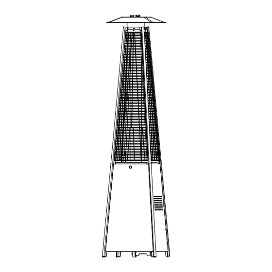
Gas- fired outdoor infrared
patio heaters
Should you have any queries, please feel free to contact us at (562)456-0507 or email to
inquiry@hykolity.com. We always find ways to improve!
If you smell gas:
1. Shut off gas to the appliance.
2. Extinguish any open flame.
3. If odor continues, keep away from the appliance
and immediately call your gas supplier or fire
department.
Do not store or use gasoline or other flammable
vapors and liquids in the vicinity of this or any other
appliance. A propane-cylinder not connected for use
shall not be stored in the vicinity of this or any other
appliance.
WARNING:
DANGER
Improper installation, adjustment, alteration, service
or maintenance can cause property damage, injury or
death. Read the installation, operation and
maintenance instructions thoroughly before installing
or servicing this equipment.
KEEP THIS MANUAL FOR FUTURE
REFERENCE
1
Owner's Manual
PATIO HEATER
SKU# WHC-0206
DANGER
WARNING
For Outdoor Use Only
CARBON MONOXIDE HAZARD
This appliance can produce
carbon monoxide which has
no odor. Using it in an enclosed
space can kill you. Never use this
appliance in an enclosed space
such as a camper, tent, car or
home.
WARNING
OUTDOOR
WHC-0207
Advertisement
Table of Contents

Related Manuals for hykolity WHC-0206


Summary of Contents for hykolity WHC-0206
- Page 1 KEEP THIS MANUAL FOR FUTURE Conforms to CSA/ANSI Z83.26-2020/CSA 2.37-2020 REFERENCE Gas- fired outdoor infrared patio heaters Should you have any queries, please feel free to contact us at (562)456-0507 or email to inquiry@hykolity.com. We always find ways to improve!
-
Page 2: Package Contents
PACKAGE CONTENTS Reflector Flame Screen Glass Tube Upper Support Protective Guard Black Silicone Ring iddle Plate Control Box Assy Lower Support Side Panel Block Belt Front Panel Wheel Assembly Gas Hose & Regulator Bottom Plate PART DESCRIPTION QUANTITY Reflector Installation Video Flame Screen Glass Tube Upper Support... -
Page 3: Hardware Contents
HARDWARE CONTENTS Wing nut Stud Small flat Flange Qty. 3 Qty. 3 Qty. 42 Qty. 4 Qty. Qty. 4 Philips Knob Qty. 1 Qty. 1 Qty. 1 Qty.1 Qty. 4 Qty. Chain Round Plate AA Battery Anchoring Arm Anchoring Qty.1 Qty.1 Qty.1 Qty.4... - Page 4 SAFETY INFORMATION DANGER DANGER • EXPLOSION - FIRE HAZARD • EXPLOSION - FIRE HAZARD • Never store propane near high heat, open flames, • Keep solid combustibles, such as building materials, pilot lights, direct sunlight, other ignition sources or paper or cardboard, a safe distance away from the where temperatures exceed 120 degrees F (49°C).
- Page 5 SAFETY INFORMATION WARNING WARNING Improper installation, adjustment, alteration, service or • This product is fueled by propane gas. Propane gas maintenance can cause property damage, injury or is invisible, odorless, and flammable. An odorant is death. Read the installation, operation and normally added to help detect leaks and can be maintenance instructions thoroughly before installing described as a “rotten egg”...
- Page 6 ASSEMBLY INSTRUCTIONS 1. Fix the Wheel Assembly(N) to the Bottom Plate(O) with 4 Bolts (EE) and 4 Flange Nuts(FF) Hardware Used Bolt M6 X 12 M6 Flange nut Wrench 2-1. Twist off the igniter button cap, load one battery(OO) on the right pole. Then place the cap back.
- Page 7 ASSEMBLY INSTRUCTIONS 3.Assemble Block Belt. Fix the Block Belt(M) to the 2pcs of lower support opposite to the front door with 2 screws(GG). Hardware Used Screw M5 X 12 Philips screwdriver 4. Assemble the Upper Support. Insert the 4pcs Upper Support(D) to the lower support at the right end(with 2 screw holes vertically).
- Page 8 ASSEMBLY INSTRUCTIONS 5. Assemble the flame screen. Secure the Flame Screen(B) to the upper support with 8 screw(DD). Hardware Used 3/16” Screw Philips screwdriver 6. Assemble the Reflector. Insert the 3 studs(CC) on the Flame Screen(B). Place 3 washer(BB) onto the stud, then thread it through the Reflector(A).
- Page 9 ASSEMBLY INSTRUCTIONS 7. Install the Glass Tube(C). a. place the black silicone ring onto the end of the glass tube as illustrated. b. insert the glass tube into the center hole of the flame screen(the 3 spring plates on the flame screen should stick onto the To aid in installation outside of the glass tube).
- Page 10 ASSEMBLY INSTRUCTIONS 9. Attach the 3 Side Panel(G) onto the lower support poles with 18 screw(DD). Note : Do not cover the front side where the control knob is. Hardware Used 3/16” Screw x 18 Philips screwdriver 10. Attach the Knob(KK) ,the Chain(MM) and the Round Plate(NN) onto the Front Panel(H) with 1 screw(LL).
- Page 11 ASSEMBLY INSTRUCTIONS 11. Connect the Gas Hose & Regulator(I) to the gas cylinder(not included). Hand-tighten the coupling nut clockwise until it comes to a full stop. Firmly tighten by hand only. Do not cross-thread. WARNING! Ensure the hose does not contact any high temperature surfaces, or it may melt and leak causing a fire.
- Page 12 OPERATION INSTRUCTIONS Leak Check WARNING • Perform all leak tests outdoors. • Extinguish all open flames. • NEVER leak test when smoking. • Do not use the heater until all connections have been leak tested and do not leak. Hose / Control Box Assy . Hose / Regulator connection connection...
- Page 13 OPERATION INSTRUCTIONS DANGER • CARBON MONOXIDE HAZARD • For outdoor use only. Never use inside house, or other unventilated or enclosed areas. This heater consumes air (oxygen). Do not use in unventilated or enclosed areas to avoid endangering your life. Caution: Do not attempt to operate until you have read and understand all General Safety Information in this manual and all assembly is complete and leak checks have been performed.
- Page 14 OPERATION INSTRUCTIONS 4. Push and release the igniter button until pilot flame is visible through the glass tube. 5. Once the pilot is lit, continue to depress the control knob for 30 seconds. 6. Push in and turn the control knob to “HIGH”(Figure 3), then release control knob. After that turn the knob as preferred to obtain the desired warmth (Figure 4).
-
Page 15: Care And Maintenance
CARE AND MAINTENANCE WARNING FOR YOUR SAFETY: • Do NOT touch or move heater for at least 45 minutes after use. • Reflector is hot to the touch. • Allow reflector to cool before touching. Maintenance To enjoy years of outstanding performance from your heater, make sure you perform the following maintenance activities on a regular basis: Keep exterior surfaces clean. -
Page 16: Troubleshooting
Turn off the heater and clean the burner with a vacuum cleaner or high pressure air blower. Customer Support Thank you for ordering our products! Should you have any queries, please feel free to contact us at (562)456-0507 or email to inquiry@hykolity.com. We always find ways to improve!
Need help?
Do you have a question about the WHC-0206 and is the answer not in the manual?
Questions and answers