JVC SP-UXP7 Service Manual
Hide thumbs
Also See for SP-UXP7:
- Instructions manual (28 pages) ,
- Instructions manual (24 pages) ,
- Instructions manual (28 pages)
Advertisement
Table of Contents
- 1 Table of Contents
- 2 Cassette Mechanism Assembly and Parts List (Block No.mp)
- 3 CD Loading Base Assembly and Parts List (Block No.MD)
- 4 CD Mechanism Assembly and Parts List (Block No.mb)
- 5 Electrical Parts List (Block No.01~06)
- 6 Packing Materials and Accessories Parts List (Block No.m3,M5)
- 7 Parts List
- Download this manual
SERVICE MANUAL
MICRO COMPONENT SYSTEM
STANDBY/ON
DIMMER
DISPLAY
SLEEP
MD/AUX
PROG
RANDOM
REPEAT
SOUND
AUTO
MODE
PRESET
FM MODE
FM/AM
TAPE
CD
CD
CANCEL
MULTI KEY
SET
AHB PRO
LEVEL
VOLUME
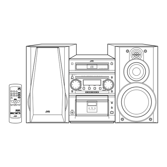
RM-SUXP7U REMOTE CONTROL
Contents
Safety precautions
Preventing static electricity
Important for laser products
Disassembly method
Main adjustment
Flow of functional operation
until TOC read (CD)
UX-P7
COMPACT
DIGITAL AUDIO
STANDBY / ON
M I C R O
C O M P O N E N T
S Y S T E M
STANDBY
/
ON
CD
TAPE
FM/AM
/
AHB PRO
SOUND
REC
A U T O R E V E R S E
PHONES
SP-UXP7
CA-UXP7
1-2
1-4
1-6
1-7
1-15
1-19
This service manual is printed on 100% recycled paper.
COPYRIGHT
2001 VICTOR COMPANY OF JAPAN, LTD.
C D - R / R W P L A Y B A C K
U X · P 7
CLOCK
MD/AUX
VOLUME
TIMER
REV .MODE
REC
SP-UXP7
A
UF
UP
US
UW
UY
Maintenance of laser pickup
Replacement of laser pickup
Description of major ICs
Internal connection of display
UX-P7
UX-P7
Area Suffix
Australia
China
Korea
Singapore
South Africa
Argentina
1-20
1-20
1-21
1-40
No.21009
1-1
Jul. 2001
Advertisement
Table of Contents


Need help?
Do you have a question about the SP-UXP7 and is the answer not in the manual?
Questions and answers