MTI 1510A Operation Manual
Calibration kit
Hide thumbs
Also See for 1510A:
- Software operation manual (50 pages) ,
- Operation and maintenance manual (45 pages)
Table of Contents
Advertisement
MTI Part Number 7000-8028
Revision 5.0 – 27 May 2014
1510A
Calibration Kit
Operation Manual
This item is PART 1 of 2 of NSN 4940-01-612-5855, PN 8000-7151-AF
This document discloses subject matter in which MTI Instruments Inc. has proprietary rights and such subject matter shall not, without
written permission of MTI Instruments Inc. be either
(a) used, released, or disclosed in whole or in part
(b) used in whole or in part for manufacture.
This legend shall be marked on any reproduction hereof in whole or in part.
MTI Instruments, Inc.
325 Washington Avenue Extension, Albany, New York 12205 USA
Phone: (518) 218-2550
█
PN 8000-7152
FAX: (518) 218-2506
█
Advertisement
Table of Contents

Related Manuals for MTI 1510A


Summary of Contents for MTI 1510A
- Page 1 This item is PART 1 of 2 of NSN 4940-01-612-5855, PN 8000-7151-AF This document discloses subject matter in which MTI Instruments Inc. has proprietary rights and such subject matter shall not, without written permission of MTI Instruments Inc. be either (a) used, released, or disclosed in whole or in part (b) used in whole or in part for manufacture.
- Page 3 MTI Part Number 7000-8028 Revision 5.0 Released 27 May 2014 1510A CALIBRATION KIT PN 8000-7152 Operation Manual This item is PART 1 of 2 of NSN 4940-01-612-5855 PN 8000-7151-AF 325 Washington Avenue Extension, Albany, New York 12205 USA...
- Page 4 Phone: (518) 218-2550 FAX: (518) 218-2506 █ █ This page was left blank intentionally.
- Page 5 1510A Calibration Kit MTI Instruments 7000-8028 LIST OF CHANGES Rev. Date Description 11/01/12 All sections released 04/11/13 All sections reformatted 05/27/14 ECN 4458 Revision 5.0 May 27, 2014...
- Page 6 MTI Instruments 7000-8028 1510A Calibration Kit This page is intentionally blank Revision 5.0 May 27, 2014...
-
Page 7: Table Of Contents
Unpacking and Inspection........... 3-1 3-1.1 Unpacking .................... 3-1 3-1.2 Initial Inspection .................. 3-2 Components of the 1510A Calibration Kit ......3-2 Installing the Support Software Package ......3-6 3-3.1 Installing the Software ................3-6 3-3.2 Installing the 1510A USB Driver ............3-7 3-3.3... - Page 8 MTI Instruments 7000-8028 1510A Calibration Kit TABLE OF CONTENTS – (Continued) Section Page OPERATION INSTRUCTIONS ........... 4-1 Operation and Use of the Kit ..........4-1 4-1.1 Calibration Kit Hardware Overview ............4-1 4-1.2 Calibration Kit Precautions ..............4-3 4-1-3 Performing the Procedures ..............4-4 1510A Acceptance Check ............
-
Page 9: Foreword
Precision Charge Adapter, several cables and software which must be loaded on a PC style computer. Using this kit to check the calibration and re-calibrate your 1510A Precision Signal Source is the only way to ensure that the charge outputs of the 1510A are accurately calibrated. - Page 10 MTI Instruments 7000-8028 1510A Calibration Kit This page has been left blank intentionally. Revision 5.0 May 27, 2014...
-
Page 11: Introduction And General Information
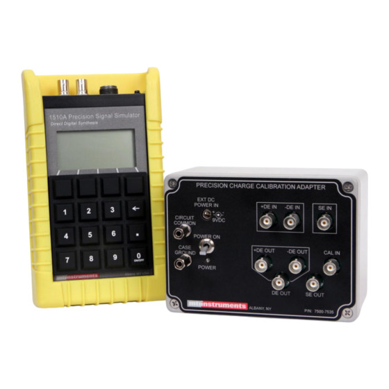
1-1.1 Purpose. The 1510A Calibration Kit illustrated below is used to check the calibration and to re-calibrate the charge outputs of the 1510A Precision Signal Source. The kit consists of a Precision Charge Calibration Adapter, a software application that runs on a Windows PC, and a variety of adapter cables. -
Page 12: 1-1.2 Basic Functional Description
1500CS which is an earlier version of the 1510A unit. The key to the 1510A Calibration Kit is the Calibration Support Software. This software package guides users thru semi-automated processes that command different output values from the device under test, and then require the operator to input voltages measured by a precision voltmeter. -
Page 13: 1-1.3 Hardware Description
1510A Precision Signal source. Major components of the 1510A Calibration Kit are illustrated in the illustration on page 1-1, and listed in the table below. Further description of the major components is provided in paragraphs 1-1.3.1 through 1-1.3.12. -
Page 14: 1-1.3.5 Single Ended Low Noise Calibration Cable
Windows operating system computer. When used, this package runs a Wizard type program to perform a calibration check or re-alignment of the 1510A under test. The software controls the 1510A, and records measured results. At the conclusion of the test, a summary report is provided to the user. -
Page 15: 1-1.3.10 Shipping And Storage Case
1-1.3.11 Operators Manual. Illustrated and labeled as item #11 in the figure on the first page of this section, this manual is provided to guide user thru the 1510A calibration check and re-calibration procedures. 1-2. CAPABILITIES AND LIMITATIONS The 1510A Calibration Kit performs the following functions: ... - Page 16 MTI Instruments 7000-8028 1510A Calibration Kit This page has been intentionally left blank Revision 5.0 May 27, 2014...
-
Page 17: Special Tools And Test Equipment
2-2 SPECIAL TOOLS Special tools are not required for general maintenance of the 1510A Calibration Kit. While there are very few user serviceable components, calibration of the Charge Calibration Adapter can be performed and some minor repairs and maintenance of connectors and cables can be accomplished using common hand tools and standard shop practices. - Page 18 MTI Instruments 7000-8028 1510A Calibration Kit This page has been left blank intentionally. Revision 5.0 May 27, 2014...
-
Page 19: Preparation For Use And Shipment
Refer to your shipping documents and verify that you have received a complete shipment. Place the 1510A Calibration Kit on a bench and inspect for any shipping damage. Contact your MTI sales representative immediately if the shipment is incorrect or incomplete. -
Page 20: Components Of The 1510A Calibration Kit
MTI Instruments 7000-8028 1510A Calibration Kit 3-2 Components of the 1510A Calibration Kit Place the1510A Calibration Kit components on a bench, and arrange them so that you can easily inspect the front and rear panels. Refer to the illustrations on the next pages to familiarize yourself with the Calibration Adapter and the various cables and accessories. - Page 21 Function Precision Charge Calibrator Adapter Precision Charge is used to Calibration Adapter support the calibration of the 1500CS and the 1510A precision signal sources. The Adapter contains precision electronic circuits that convert charge signal into voltage signals. AC Power Adapter This AC power adapter is used to power the Precision Charge Calibrator Adapter.
- Page 22 MTI Instruments 7000-8028 1510A Calibration Kit PRECISION CHARGE CALIBRATION ADAPTER Precision Calibration Adapter Front Panel Components Index Item Function Precision Charge Calibrator Adapter External DC Power Input can operate from an internal 9 volt battery, or from the external power adapter.
- Page 23 Ended Charge calibrations. Refer to Section 4 of this manual for procedures. USB Cable P/N 6000-2001 This three (3) foot long cable is used to connect the 1510A under test to the control computer. This cable will transmit control commands and data between the unit under test and the control PC running the Calibration Support Software.
- Page 24 1510A Calibration Kit Calibrator Support Software Package - The Calibrator Support Software Package has been designed to help automate the calibration and re-calibration (re-alignment) of 1510A Precision signal sources. In addition to supporting the calibration testing, it also supports several other functions.
-
Page 25: 3-3.1 Installing The Software
1510A Calibration Kit MTI Instruments 7000-8028 3-3 Installing the 1510A Calibration Support Software Package – The 1510A Calibration kit includes a CD-ROM that contains application software required to perform the semi-automated calibration checks and re-calibration of the 1510A Precision Signal sources. -
Page 26: 3-3.2 Installing The 1510A Usb Driver
USB folder located on the CDROM, copy it and save it in your Windows\INF folder. After verifying that the INF file exists, connect the USB cable to the 1510A and connect it to an unused USB port on your computer. -
Page 27: 3-3.3 Identification Of The Usb Port
3-3.3 Identification of the USB Port The Calibration Support Software program also needs to know to which USB port the 1510A is connected. To perform this part of the installation, follow these steps: Click Start-Settings-Control Panel and double click the System icon. When the System Properties dialog... -
Page 28: 3-3.4 Setting Up The Support Software Initialization File
First, verify that the Serial Port number listed in the INI file is correct for your system. 1=COM1, 2=COM2, etc. When setting up the software for a 1510A device, set the PORT2 value to the port number previously determined from Device Manager. -
Page 29: Preparation For Storage And Shipment
3-4.2 Preparation for Shipment. To protect the equipment during shipment, use packaging materials appropriate for electronic instrumentation. If returning the 1510A Calibration Kit to the factory, place all of the items into the shipping and storage case, and then place the case into a strong carton rated for 0.25kg/mm (350 lbs/in burst strength, minimum or other suitable shipping container. -
Page 30: Battery Installation And Replacement
MTI Instruments 7000-8028 1510A Calibration Kit 3.5 BATTERY INSTALLATION and REPLACEMENT This procedure provides instructions for installing or replacing the internal 9 volt battery found inside the Precision Charge Calibration Adapter. For this procedure, refer to the identification diagram provided along with the following step- by-step instructions. -
Page 31: Operation Instructions
OPERATING INSTRUCTIONS 4-1 OPERATION AND USE OF THE KIT The 1510A Calibration Kit is an easy to use system for the checking the accuracy of and re- calibration (alignment) of 1510A precision signal sources. The kit includes software, accessory cables, and a unique charge calibration adapter which allow users to perform semi-automated checking of the accuracy of the 1510A signal source and when required, re-calibration (alignment) may also be performed. -
Page 32: 4-1.2 Calibration Kit Precautions
Precision Charge Calibration Adapter device that converts the 1510A charge signals to voltages. The outputs of the Precision Charge Calibration Adapter are then sent to the precision DVM where measurements are recorded by the calibration support software. - Page 33 Use high quality cables – All cables used for the testing and calibration (alignment) of the 1510A units should be of the highest quality and as short as practical. Due to the low levels of signals being generated and measured, cables need to be as short a possible. Electrical noise susceptibility can also be an issue when working with charge signals, and these connections demand special low-noise cables that are properly shielded.
- Page 34 Section 4-2 provides instructions for performing an Acceptance Check of a 1510A device. An acceptance Check tests the accuracy of the outputs of the 1510A and concludes with a summary table which indicates in and out of tolerance conditions of the device.
-
Page 35: 1510A Acceptance Check
4-2.1 Introduction and Overview – The 1510A Acceptance Check provides users with a fast and easy way to assess the accuracy of the 1510A unit. This check is semi-automatically performed by the 1510A Acceptance Check Wizard which is a part of the Support software package. -
Page 36: 4-2.3 Selecting The Device Type
If the software has not yet been loaded, refer to section 3.3 of this manual. At the computer, double clicking on the icon will launch the 1510A Support Program. An introductory display will first be visible for a few seconds:... - Page 37 1510A device. Users simply need to follow the instructions displayed on each page, and when completed, click the NEXT button. To check a 1510A unit you will need a high accuracy voltmeter and the cables listed. Revision 5.0 May 27, 2014...
-
Page 38: 4-2.6 Connect To Channel A
Connection to the 1510A Before continuing, ensure that the USB communications cable has been connected between the 1510A and the computer that is running the Acceptance Check Wizard. Ensure that the 1510A is on. After the connection has been made press Next button. - Page 39 1510A Calibration Kit MTI Instruments 7000-8028 Channel A Low DC range #1 check Click in the Voltage Reading window and enter the reading of the voltmeter. Verify that the meter has been set for DC voltage measurement. After entering the reading, continue by...
- Page 40 MTI Instruments 7000-8028 1510A Calibration Kit Channel A mid DC range #1 check Next, click in the Voltage Reading window and enter the reading of the voltmeter. Verify that the meter has been set for DC voltage measurement. After entering the reading, continue by...
- Page 41 1510A Calibration Kit MTI Instruments 7000-8028 Channel A high DC range #2 check Next, click in the Voltage Reading window and enter the reading of the voltmeter. Verify that the meter has been set for DC voltage measurement. After entering the reading, continue by...
- Page 42 MTI Instruments 7000-8028 1510A Calibration Kit Channel A mid AC range #1 check Next, click in the Voltage Reading window and enter the reading of the voltmeter. Verify that the meter has been set for AC rms voltage measurement. After entering the reading, continue by...
- Page 43 1510A Calibration Kit MTI Instruments 7000-8028 Channel A high AC Range #2 check Next, click in the Voltage Reading window and enter the reading of the voltmeter. Verify that the meter has been set for AC rms voltage measurement. After entering the reading, continue by...
-
Page 44: 4-2.7 Channel B Checks
MTI Instruments 7000-8028 1510A Calibration Kit 4-2.7 Channel B checks Next, connect the 7500-7533 cable to the 1510A Channel B output connector and to the input of the voltmeter. Verify that the meter has been set for AC rms voltage measurement. - Page 45 1510A Calibration Kit MTI Instruments 7000-8028 Channel B mid AC range#1 AC check Next, click in the Voltage Reading window and enter the reading of the voltmeter. Verify that the meter has been set for AC rms voltage measurement. After entering the reading, continue by...
-
Page 46: 4-2.8 Single Ended Charge Accuracy Check
Next pressing the button. 4-2.8 Single Ended charge accuracy check – Next, connect the 1510A to the voltmeter as illustrated using the special charge calibration adapter and associated cables. Set the voltmeter for AC RMS readings. When all cables have been connected,... - Page 47 1510A Calibration Kit MTI Instruments 7000-8028 Single Ended Low Range #2 charge check Next, click in the Voltage Reading window and enter the reading of the voltmeter. Verify that the meter has been set for AC rms voltage measurement. After entering the reading, continue by...
- Page 48 Next pressing the button. 4-2.9 Differential charge Acceptance check Next, connect the 1510A to the voltmeter as illustrated using the special charge calibration adapter and associated cables. Set the voltmeter for AC RMS readings. When all cables have been connected,...
- Page 49 1510A Calibration Kit MTI Instruments 7000-8028 NOTE To ensure accuracy, do not allow the cables to move during this series of tests. Even small motion of the cable can induce measurement errors. NOTE The DE output cable has shield drain banana plugs at each end of the cable.
- Page 50 MTI Instruments 7000-8028 1510A Calibration Kit Differential Mid Range #1 charge check Next, click in the Voltage Reading window and enter the reading of the voltmeter. Verify that the meter has been set for AC rms voltage measurement. After entering the reading, continue by...
-
Page 51: 4-2.10 Reviewing The Accuracy Check Results
1510A Calibration Kit MTI Instruments 7000-8028 Differential High Range #2 charge check Next, click in the Voltage Reading window and enter the reading of the voltmeter. Verify that the meter has been set for AC rms voltage measurement. After entering the reading, continue... -
Page 52: 4-2.11 Updating The Internal Memory
4-2.11 Updating the internal memory The 1510A has an internal memory where the latest calibration date can be saved. If the unit has passed the Acceptance check, the memory should be updated before the unit is returned to service. - Page 53 Next, click on the function at the top of the display and Download to Unit select the function as illustrated. This will send the new calibration date to the 1510A unit. Answer to the “Are you sure” question. In a few seconds, you will receive the Confirmation of a successful download.
- Page 54 MTI Instruments 7000-8028 1510A Calibration Kit This page is intentionally blank. 4-24 Revision 5.0 May 27, 2014...
-
Page 55: 1510A Calibration Wizard
4-3.1 Introduction and Overview – The 1510A Calibration Wizard provides users with a fast and easy way to re-calibrate the 1510A unit to factory levels of precision. This check is semi-automatically performed by the 1510A Calibration Wizard which is a part of the Calibration Support software package. -
Page 56: 4-3.2 Starting The Software
If the software has not yet been loaded, refer to section 3.2.1 of this manual. At the computer, double clicking on the icon will launch the 1510A Support Program. An introductory display will first be visible for a few seconds:... -
Page 57: 4-3.4 Selecting The Calibration Wizard
1510A device. Users simply need to follow the instructions displayed on each page, and when completed, click the NEXT button. To calibrate a 1510A unit you will need a high accuracy voltmeter and the cables listed. 4-27 Revision 5.0 May 27, 2014... -
Page 58: 4-3.5 Interrogating The Unit Under Test
1510A and the computer that is running the Calibration Wizard. After making the connection, turn the 1510A on. After turning the 1510A on, continue by Next pressing the button. 4-3.5 Interrogating the unit under test The next step in the Calibration Wizard uploads the units’... -
Page 59: 4-3.6 Starting The Channel A Low Range Ac Calibration
1510A Calibration Kit MTI Instruments 7000-8028 4-3.6 Starting the Channel A Low range AC calibration Click in the Voltage Reading window and enter the reading of the voltmeter. Verify that the voltmeter is set for AC RMS readings. NOTE – If your voltmeter is not... - Page 60 MTI Instruments 7000-8028 1510A Calibration Kit Channel A mid range #1 AC calibration Next, click in the Voltage Reading window and enter the reading of the voltmeter. Verify that the voltmeter is set for AC RMS readings. After entering the reading, continue by...
- Page 61 1510A Calibration Kit MTI Instruments 7000-8028 Channel A high range #1 AC calibration Next, click in the Voltage Reading window and enter the reading of the voltmeter. Verify that the voltmeter is set for AC RMS readings. After entering the reading, continue by...
- Page 62 MTI Instruments 7000-8028 1510A Calibration Kit Channel A DC offset calibration Next, click in the Voltage Reading window and enter the reading of the voltmeter. Set the voltmeter for DC volts readings. After entering the reading, continue by Next pressing the button.
- Page 63 1510A Calibration Kit MTI Instruments 7000-8028 Channel A DC Slope Low Range #3 calibration Next, click in the Voltage Reading window and enter the reading of the voltmeter. Verify that the voltmeter is set for DC voltage readings. After entering the reading, continue by...
- Page 64 MTI Instruments 7000-8028 1510A Calibration Kit Channel A DC Slope Mid Range #3 calibration Next, click in the Voltage Reading window and enter the reading of the voltmeter. Verify that the voltmeter is set for DC voltage readings. After entering the reading, continue by...
- Page 65 1510A Calibration Kit MTI Instruments 7000-8028 Channel A DC Slope High Range #3 calibration Next, click in the Voltage Reading window and enter the reading of the voltmeter. Verify that the voltmeter is set for DC voltage readings. After entering the reading, continue by...
-
Page 66: 4-3.7 Starting The Channel B Calibration
4-3.7 Starting the Channel B calibration Next, connect the 7500-7533cable to the 1510A Channel B output connector and the input to the voltmeter. Set the voltmeter for AC RMS readings. After moving the cable, continue by Next pressing the button. - Page 67 1510A Calibration Kit MTI Instruments 7000-8028 Channel B Low range#1 AC calibration Next, click in the Voltage Reading window and enter the reading of the voltmeter. Verify that the voltmeter is set for AC RMS readings. After entering the reading, continue by...
- Page 68 MTI Instruments 7000-8028 1510A Calibration Kit Channel B Mid range #1 AC calibration Next, click in the Voltage Reading window and enter the reading of the voltmeter. Verify that the voltmeter is set for AC RMS readings. After entering the reading, continue by...
- Page 69 1510A Calibration Kit MTI Instruments 7000-8028 Channel B high #1 AC calibration Next, click in the Voltage Reading window and enter the reading of the voltmeter. Verify that the voltmeter is set for AC RMS readings. After entering the reading, continue by...
-
Page 70: 4-3.8 Starting The Single Ended Charge Calibration
MTI Instruments 7000-8028 1510A Calibration Kit 4-3.8 Starting the Single Ended charge calibration – Next, connect the 1510A to the voltmeter as illustrated using the charge calibration adapter and associated cables. Set the voltmeter for AC RMS readings. When all cables have been connected,... - Page 71 1510A Calibration Kit MTI Instruments 7000-8028 Low Range #2 Single Ended charge calibration Next, click in the Voltage Reading window and enter the reading of the voltmeter. Verify that the voltmeter is set for AC RMS readings. After entering the reading, continue by...
- Page 72 MTI Instruments 7000-8028 1510A Calibration Kit Mid Range #2 Single Ended charge calibration Next, click in the Voltage Reading window and enter the reading of the voltmeter. Verify that the voltmeter is set for AC RMS readings. After entering the reading, continue by...
-
Page 73: 4-3.9 Starting The Differential Charge Calibration
Next pressing the button. 4-3.9 Starting the Differential charge calibration – Next, connect the 1510A to the voltmeter as illustrated using the special charge calibration adapter and associated cables. Set the voltmeter for AC RMS readings. When all cables have been connected,... - Page 74 MTI Instruments 7000-8028 1510A Calibration Kit NOTE To ensure accuracy, do not allow the cables to move during this series of tests. Even small motion of the cable can induce measurement errors. NOTE The DE output cable has shield drain banana plugs at each end of the cable.
- Page 75 1510A Calibration Kit MTI Instruments 7000-8028 Low Range #3 Differential charge calibration Next, click in the Voltage Reading window and enter the reading of the voltmeter. Verify that the voltmeter is set for AC RMS readings. After entering the reading, continue by...
- Page 76 MTI Instruments 7000-8028 1510A Calibration Kit Mid Range #3 Differential charge calibration Next, click in the Voltage Reading window and enter the reading of the voltmeter. Verify that the voltmeter is set for AC RMS readings. After entering the reading, continue by...
-
Page 77: 4-3.10 Reviewing And Downloading Calibration Factors
Low range, Mid range and High range numbers are near 1.000 and that the offset factors are near 0.0000. For the 1510A, verify that the Phase is near zero. Calibration factors should nominally be near 1.0000, with an allowable range from 0.9000 to 1.1000. - Page 78 After all saving and recording has been NEXT accomplished, click the button. Calibration has been completed FINISH Click the button. This is the end of the 1510A Calibration Wizard Procedure 4-48 Revision 5.0 May 27, 2014...
Need help?
Do you have a question about the 1510A and is the answer not in the manual?
Questions and answers