Advertisement
Quick Links
EVCO S.p.A. | EPcolor M & L | Instruction sheet ver. 2.1 | Code 104PCLRUPMLE213 | Page 1 of 2 | PT 15/23
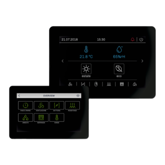
EPcolor M & L
EN
ENGLISH
-
back-panel, panel or wall mounting (according to the model)
-
24 VAC/12... 30 VDC power supply not insulated
-
5 or 7 in colour touch-screen TFT graphic display (according to the model)
-
clock
-
alarm buzzer
-
2 RS-485 MODBUS ports
-
CAN port
-
1 MB program memory
-
device for indoor applications.
Purchasing codes
Series
Display size
EPCM90X4
EPcolor M
EPCM91X4
EPcolor M
EPCM94X4V
EPcolor M
EPCL90X4
EPcolor L
EPCL91X4
EPcolor L
EPCL94X4V
EPcolor L
For further information please consult the hardware manual.
1
MEASUREMENTS AND INSTALLATION | Measurements in mm (in)
1.1
Measurements and installation EPcolor M
1.1.1
Models for back-panel mounting
Back-panel mounting, with threaded studs.
1.1.2
Models for panel and wall mounting
N.B.
- the thickness of a metal panel must be between 0.8 and 1.5 mm (1/32 and 1/16
in), while that for a plastic panel must be between 0.8 and 3.4 mm (1/32 and
1/8 in)
- the measurements of drilling template of the panel must be 130 x 88.4 mm (5 1/8
x 3 1/2 in), with rounded corners R 3.0 mm (1/8 in)
- 34.0 (1 5/16) is the depth for models for wall mounting.
Panel mounting: to be fitted to a panel, with elastic holding flaps.
Wall mounting: with bolts and fastening screws. Position the back shell so that the arrow above
the writing TOP points upwards.
Programmable (with UNI-PRO graphic tool) remote user interfaces
1.2
Measurements and installation EPcolor L
1.2.1
Models for back-panel mounting
Installation mode
Back-panel mounting, with threaded studs.
5 in
back-panel mounted
5 in
panel mounted
1.2.2
Models for panel and wall mounting
5 in
wall mounted
7 in
back-panel mounted
N.B.
7 in
panel mounted
- the thickness of a metal panel must be between 0.8 and 1.5 mm (1/32 and 1/16 in), while that for a plastic panel must be between 0.8 and 3.4 mm (1/32 and
7 in
wall mounted
1/8 in)
- the measurements of drilling template must be 178.2 x 118.2 mm (7 x 4 5/8 in), with rounded corners R 3.0 mm (1/8 in).
Panel mounting: to be fitted to a panel, with elastic holding flaps.
Wall mounting: with bolts and fastening screws. Position the back shell so that the arrow above the writing TOP points upwards.
INSTALLATION PRECAUTIONS
-
Ensure that the working conditions are within the limits stated in the TECHNICAL SPECIFICATIONS section
Do not install the device close to heat sources, equipment with a strong magnetic field, in places subject to direct sunlight, rain, damp, excessive dust, mechanical vibrations or shocks
-
In compliance with safety regulations, the device must be installed properly to ensure adequate protection from contact with electrical parts. All protective parts must be fixed in such a
-
way as to need the aid of a tool to remove them.
2
ELECTRICAL CONNECTION
N.B.
- Use cables of an adequate section for the current running through them
- To reduce any electromagnetic interference connect the power cables as far away as possible from the signal cables and connect to a CAN network and RS-485 MODBUS network by
using a twisted pair.
- do not supply another device with the same transformer
- for the CAN of EPcolor M port use a ferrite (for example Essentra RKCF-08-A5) to which the conductors of the shielded cable must be wound with two coils.
2.1
Electrical connection EPcolor M
2.1.1
Connectors and parts
Connector 1
N.
DESCRIPTION
PE
grounding equipment
PE
grounding equipment
Connector 2
N.
DESCRIPTION
36
GND reference device power supply and RS-485 MODBUS master port
35
RS-485 MODBUS master port signal -
34
RS-485 MODBUS master port signal +
33
device power supply (24 VAC/12... 30 VDC)
Connector 3
N.
DESCRIPTION
30
GND reference RS-485 MODBUS slave port
31
RS-485 MODBUS slave port signal -
32
RS-485 MODBUS slave port signal +
Connector 4
N.
DESCRIZIONE
27
GND reference CAN port
28
CAN port signal -
29
CAN port signal +
Advertisement

Related Manuals for Evco EPcolor M


Summary of Contents for Evco EPcolor M
- Page 1 - do not supply another device with the same transformer - for the CAN of EPcolor M port use a ferrite (for example Essentra RKCF-08-A5) to which the conductors of the shielded cable must be wound with two coils. Electrical connection EPcolor M 2.1.1...
- Page 2 EVCO S.p.A. | EPcolor M & L | Instruction sheet ver. 2.1 | Code 104PCLRUPMLE213 | Page 2 of 2 | PT 15/23 Connector 5: USB port, for programming the device. TECHNICAL SPECIFICATIONS Micro-switch 1: Purpose of the control device Function controller to insert the RS-485 MODBUS master port termination resistor.
Need help?
Do you have a question about the EPcolor M and is the answer not in the manual?
Questions and answers