Table of Contents
Advertisement
Quick Links
Advertisement
Table of Contents

Related Manuals for PAW SolexMini TW

Summary of Contents for PAW SolexMini TW
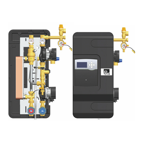
- Page 1 PAW GmbH & Co. KG Böcklerstraße 11, 31789 Hameln, Germany Phone: +49-5151-9856-0, Fax: +49-5151-9856-98 E-mail: info@paw.eu, Web: www.paw.eu Installation and Operation Instructions Transfer station SolexMini TW - DN 15 [Hydraulics] 05/2024 996091426-mub-en - V02...
-
Page 2: Table Of Contents
Scope of delivery [specialist]..................26 Spare parts primary circuit SolexMini...............26 Spare parts secondary circuit SolexMini..............27 Technical data......................30 Dimensional drawing SolexMini TW................. 31 Pressure drop and pump characteristic curves SolexMini TW........31 Function of the check valves [Expert]............... 32 Disposal........................34 Commissioning report....................35 05/2024... -
Page 3: General Information
1.1 About these instructions These instructions describe the functioning, installation, commissioning and operation of the SolexMini TW transfer station. The chapters called [specialist] are intended for specialists only. For other components of the solar installation, such as pumps, collectors, storage tanks or expansion tanks, please observe the instructions of the corresponding manufacturer. -
Page 4: About This Product
General Information 1.2 About this product The station is a premounted group of valves and fittings checked for leakage and used to transfer the heat from the primary circuit (solar circuit) to the secondary circuit (storage tank or domestic hot water circuit). -
Page 5: Designated Use
This product complies with the relevant directives and is therefore labelled with the CE mark. The Declaration of Conformity is available upon request, please contact the manufacturer. Only use PAW accessories with the transfer station. NOTICE Under the influence of solar radiation, the collectors will heat up considerably. -
Page 6: Safety Instructions
Safety instructions 2 Safety instructions The installation and commissioning as well as the connection of electrical components require technical knowledge commensurate with a recognised vocational qualification as a fitter for plumbing, heating and air conditioning technology, or a profession requiring a comparable level of knowledge [specialist]. - Page 7 Safety instructions CAUTION Risk of burns! The valves and fittings and the pumps can become heated up to more than 100 °C during operation. The insulating shell must remain closed during operation. ► CAUTION Personal injury and material damage due to overpressure! Closing both ball valves in the primary circuit will separate the safety group from the heat exchanger.
-
Page 8: Mounting And Installation [Specialist]
Mounting and installation [specialist] 3 Mounting and installation [specialist] NOTICE Material damage due to high temperatures! Since the solar fluid near the collector can be very hot, the group of fittings must be installed at a sufficient distance from the collector field. It may be necessary to install an intermediate tank in order to protect the expansion tank. - Page 9 Mounting and installation [specialist] Accessories: compression fitting 1. Push the union nut ② and the cutting ring ③ onto the copper pipe ①. The pipe must protrude at least 3 mm from the cutting ring in order to ensure the force transmission and the sealing.
- Page 10 Mounting and installation [specialist] 1. Remove the station from the packaging. 2. Remove the insulating front shell. 3. Mount the safety group consisting of safety valve [c], drain valve [f] and pressure gauge [e] on the connection of the return ball valve [b]. 4.
- Page 11 Mounting and installation [specialist] 8. Connect the transfer station to the installation by using the piping: ① Solar flow from the collector ② Solar return to the collector ③ Flow to the storage tank ④ Return from the storage tank All thread connections have ¾"...
- Page 12 Mounting and installation [specialist] WARNING Risk to life and limb due to electric shock! Prior to commencing electrical work on the controller, pull the mains plug! ► Only after completing all installation work as well as the flushing and filling, ►...
-
Page 13: Commissioning [Specialist]
Commissioning [specialist] 4 Commissioning [specialist] Please observe the following safety instructions regarding the commissioning of the station: WARNING Risk of burning and scalding! The valves and fittings may heat up to more than 100 °C. Therefore, do not clean or fill the system when the collectors are hot (intense sunshine). - Page 14 Commissioning [specialist] NOTICE Note regarding the expansion tank The expansion tank must not be connected while flushing and filling in order to prevent dirt particles from being flushed in. Please observe the instructions of the manufacturer. 996091426-mub-en - V02 05/2024...
-
Page 15: Flushing And Filling The Secondary Circuit
Commissioning [specialist] 4.1 Flushing and filling the secondary circuit Depending on the application, the secondary circuit is filled (charging of a domestic hot water tank) via the valves at the domestic hot water tank or (charging of a buffer tank) via the valves of the heating installation. -
Page 16: Flushing And Filling The Solar Circuit
Commissioning [specialist] 4.2 Flushing and filling the solar circuit The fill and drain valves required to flush and fill the installation are integrated in the transfer station. Make sure that dirt particles that may be present in the system are not flushed into the heat exchanger and into the expansion tank. - Page 17 Commissioning [specialist] Functions of the fill and drain valve within the safety group Position Function Position "closed" (station in operation): Fill and flush circuit is closed. Pressure gauge indicates system pressure. Position "open" (fill and flush processes): Fill and flush circuit is open. Pressure gauge indicates pressure. Position "maintenance"...
- Page 18 Commissioning [specialist] Airstop The Airstop (with manual vent valve) is used to vent the solar system. To ensure a perfect venting of the solar circuit, the flow velocity must be at least 0.3 m/s in the flow line. Pipe diameter [mm] Flow rate at 0.3 m/s l/min ∅...
- Page 19 Commissioning [specialist] Flushing and filling 1. Switch off the pump of the solar circuit. 2. Disconnect the expansion tank from the solar system. This prevents dirt particles still present in the pipes from being flushed into the expansion tank. Observe the separate instructions for the expansion tank! 3.
- Page 20 Commissioning [specialist] Close the drain valve [f] with the filling pump running, see section Functions of the fill and drain valve within the safety group and increase the system pressure to about 5 bars. The system pressure is displayed on the pressure gauge [e].
- Page 21 Commissioning [specialist] 16. Connect the controller to the mains and set the solar circuit pump in manual mode to ON according to the controller instructions. 17. Let the solar circuit pump run at maximum rotation speed for at least 15 minutes. In the meantime, vent the solar system several times at the vent plug [k] of the airstop until the SC5.14...
-
Page 22: Parameters Of The Controller Sc5.14
Commissioning [specialist] 4.3 Parameters of the controller SC5.14 The parameters for the sensors and pumps are preset in the controller. If another system is selected and saved, the parameters are reset to the factory settings. In this case, the parameters must be modified in the menu. -
Page 23: Maintenance [Specialist]
Maintenance [specialist] 5 Maintenance [specialist] WARNING Risk of burning and scalding! The valves and fittings and the solar fluid can have temperatures of more than 100 °C. The solar fluid may escape as vapour and result in scalding. Perform maintenance work only when the collector temperatures are ►... -
Page 24: Maintenance Work
Maintenance [specialist] 5.2 Maintenance work Depressurise the installation for all replacement or service work on the station. This does not apply to the replacement of the pressure gauge. 1. Close the ball valves [a|b] and release the solar fluid at the fill and drain valve [i]. Make sure that the solar fluid is collected in a heat-resistant container. -
Page 25: Deinstallation
Maintenance [specialist] WARNING Danger of scalding due to hot solar fluid! The escaping solar fluid can be very hot! Position and secure the heat-resistant collecting container such that persons ► nearby are not put at risk when the solar system is drained. 4. -
Page 26: Scope Of Delivery [Specialist]
Scope of delivery [specialist] 6 Scope of delivery [specialist] NOTICE Serial number Complaints and requests/orders of spare parts will only be processed with information on the serial number! The serial number is placed on the safety group. In case of a complaint, please send us the entirely completed commissioning report. ►... -
Page 27: Spare Parts Secondary Circuit Solexmini
Scope of delivery [specialist] 6.2 Spare parts secondary circuit SolexMini 05/2024 996091426-mub-en - V02... - Page 28 Scope of delivery [specialist] Position Spare part Item number Sealing kit, 24.0 x 17.0 x 2.0, ¼", for thread connection ¾", 10 pieces N00030 Safety bar DN 20, fill and drain valve ½" N00462 Pressure relief valve ½" x ¾", 6 bars N00300 Fill and drain valve ½", ¾"...
- Page 29 Scope of delivery [specialist] Position Spare part Item number Sealing kit, 30.0 x 21.0 x 2.0, ½", for thread connection 1", EPDM, N00129 10 pieces Pump Grundfos UPM4 15-70 CIL3, 130 mm, 6 o'clock, 1" ext. thread, N00383 PWM-C, suitable for DHW without Platinum measuring sensor Pt1000-B, -50 °C up to 105 °C, d = 6 mm, N00358...
-
Page 30: Technical Data
Technical data 7 Technical data Dimensions SolexMini TW Total height 681 mm Total width 417 mm Total depth 249 mm Centre distance flow / return 82 mm Pipe connections ¾" internal thread Connection for expansion tank ¾" external thread, flat sealing Outlet of pressure relief valve ¾"... -
Page 31: Dimensional Drawing Solexmini Tw
Technical data 7.1 Dimensional drawing SolexMini TW 7.2 Pressure drop and pump characteristic curves SolexMini TW 05/2024 996091426-mub-en - V02... -
Page 32: Function Of The Check Valves [Expert]
Function of the check valves [Expert] 8 Function of the check valves [Expert] The check valves in this station prevent unwanted gravity circulation within their range of use. The functioning of the check valves depends: on the system height ● on the temperature difference between storage tank and collector ●... - Page 33 Function of the check valves [Expert] Do you need to know it exactly? The density of the solar fluid strongly decreases with increasing temperature. In systems of high system heights and with large temperature differences, the difference in density causes gravity circulation.
-
Page 34: Disposal
Disposal 9 Disposal NOTICE Electrical and electronic devices must not be disposed of in the household waste. For your return, there are free collection points for electrical appliances and, if necessary, additional points of acceptance for the reuse of the devices in your area. The addresses can be obtained from your city or communal administration. -
Page 35: Commissioning Report
Commissioning report 10 Commissioning report System operator Location of installation Collectors (number / type) Collector surface m² System height m (height difference between the station and the collector field) Pipeline diameter = length = Venting (collector field) not available vented manual vent valve automatic vent valve Airstop (station) - Page 36 Böcklerstraße 11 31789 Hameln, Germany Translation of the original instructions www.paw.eu We reserve the right to make technical changes without notice! Phone: +49-5151-9856-0 Printed in Germany – Copyright by PAW GmbH & Co. KG Fax: +49-5151-9856-98 05/2024 996091426-mub-en - V02...
Need help?
Do you have a question about the SolexMini TW and is the answer not in the manual?
Questions and answers