Table of Contents
Advertisement
Quick Links
Advertisement
Table of Contents

Related Manuals for PCB Piezotronics 477A06


Summary of Contents for PCB Piezotronics 477A06
- Page 1 Model 483C28/477A06 SIGNAL CONDITIONER Installation and Operating Manual For assistance with the operation of this product, contact PCB Piezotronics, Inc. Toll-free: 800-828-8840 24-hour SensorLine: 716-684-0001 Fax: 716-684-0987 E-mail: info@pcb.com Web: www.pcb.com...
- Page 2 Piezotronics, user servicing or repair is critical test. not recommended and, if attempted, may void the factory warranty. Routine PCB Piezotronics maintains an ISO- maintenance, such as the cleaning of 9001 certified metrology laboratory and electrical connectors, housings, and offers calibration services, which are...
- Page 3 50% of the general contact numbers are: replacement cost returned item(s). PCB will provide a price PCB Piezotronics, Inc. quotation replacement 3425 Walden Ave. recommendation for any item whose Depew, NY14043 USA repair costs would exceed 50% of...
- Page 4 PCB工业监视和测量设备 - 中国RoHS2公布表 PCB Industrial Monitoring and Measuring Equipment - China RoHS 2 Disclosure Table 有害物质 汞 镉 六价铬 (Cr(VI)) 多溴联苯 (PBB) 多溴二苯醚 (PBDE) 部件名称 铅 (Pb) (Hg) (Cd) 住房 PCB板 电气连接器 压电晶体 环氧 铁氟龙 电子 厚膜基板 电线 电缆 塑料 焊接...
- Page 5 Component Name Hazardous Substances Lead Mercury Cadmium Chromium VI Polybrominated Polybrominated (Pb) (Hg) (Cd) Compounds Biphenyls Diphenyl (Cr(VI)) (PBB) Ethers (PBDE) Housing PCB Board Electrical Connectors Piezoelectric Crystals Epoxy Teflon Electronics Thick Film Substrate Wires Cables Plastic Solder Copper Alloy/Brass This table is prepared in accordance with the provisions of SJ/T 11364.
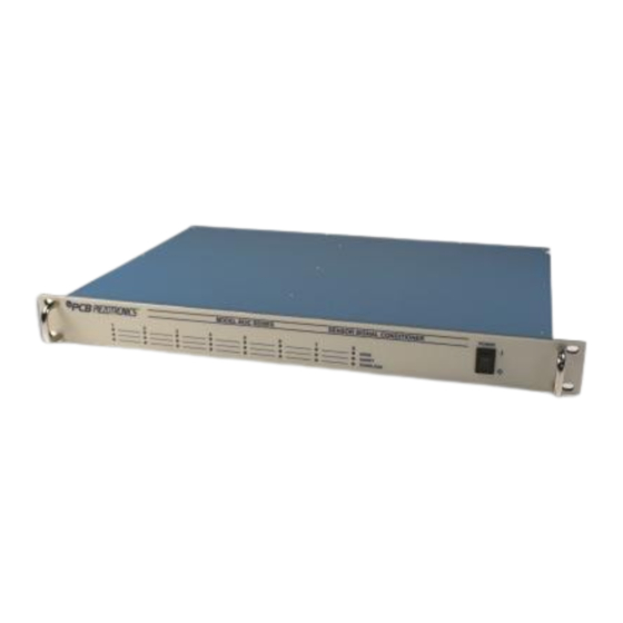
- Page 6 A front panel interface is also provided for standalone operation. 43998 Manual Revision: A ECO: 49597 PCB PIEZOTRONICS, INC. 3425 WALDEN AVENUE DEPEW, NY 14043-2495 PHONE 716-684-0001 FAX 716-684-0987 ® ICP is a registered trademark of PCB Group, Inc. KS398...
-
Page 7: Table Of Contents
Table of Contents Table of Contents INTRODUCTION AND SPECIFICATIONS Introduction: Safety Considerations Model 483C System Description ® 1-2.1 Model 483C ICP Input/Output Mode, All Models Block Diagram Installation 1-4.1 Grounding Techniques 1-4.2 Quick Set-up Instructions Operation: Standard AC Line THEORY OF OPERATION Sensor Excitation Input Protection Input Fault Detection... - Page 8 MULTICHANNEL SIGNAL CONDITIONER MODEL 482C GENERAL OPERATION MANUAL Model 483C Communication Guidelines Command Summary Command Format Multiple Board Models Commands GAIN SENS FSCI FSCO INPT IEXC VEXC FLTR OFLT CLMP CPLG SWOT CALB RTED ALLC RBIA CHRD STUS UNIT UNID AZZR LEDS RSET...
- Page 9 MULTICHANNEL SIGNAL CONDITIONER MODEL 482C GENERAL OPERATION MANUAL RSE / NRSE Mode for 3 Wire Sensors Connection of Triaxial Sensors Figure 1 Typical Block Diagram of Model 483C28 ..........3 ® Figure 2 ICP Sensor Excitation .................5 Figure 3 Input Fault Window Comparator with LED Indicator ......6 Figure 4 Input Amplifier Configuration...............6 Figure 5 Selectable Gain Amplifier Configuration ..........6 Figure 6 Autoscale/Overload Window Comparator .........8...
-
Page 10: Introduction And Specifications
WARNING 2: This equipment is designed with user safety in mind; however, the protection provided by the equipment may be impaired if the equipment is used in a manner not specified by PCB Piezotronics, Inc. Caution 1: Cables can kill your equipment. High voltage Electro Static Discharge (ESD) can damage electrical devices. -
Page 11: Model 483C System Description
MULTICHANNEL SIGNAL CONDITIONER MODEL 483C28 GENERAL OPERATION MANUAL EQUIPMENT RATINGS For complete specifications, please refer to the enclosed Specification Sheet. This equipment operates optimally at +32 to +120°F (0 to +50°C), in an environment having <85% relative humidity. Its line power frequency range is 50/60 Hz. -
Page 12: Block Diagram
MULTICHANNEL SIGNAL CONDITIONER MODEL 483C28 GENERAL OPERATION MANUAL The Model 483C contains a regulated 24 VDC power supply that provides constant current for up to 8 individual channels. Both the output and input connections utilize BNC connectors and are brought out through the rear panel. -
Page 13: 1-4.2 Quick Set-Up Instructions
MULTICHANNEL SIGNAL CONDITIONER MODEL 483C28 GENERAL OPERATION MANUAL specification of noise and reduce the effects of line interference, proper grounding techniques should be used. The following procedure may be helpful: 1. Make sure the signal ground lines of all equipment are tied together. The signal grounds of the channels are typically tied together via the case of the input and output BNC connectors. -
Page 14: Theory Of Operation
MULTICHANNEL SIGNAL CONDITIONER MODEL 483C28 GENERAL OPERATION MANUAL Reference THEORY OF OPERATION Sensor Excitation ® refers to a low output impedance voltage mode sensor combining an integrated circuit and a piezoelectric sensing element in a single housing to provide a voltage output. This sensor is powered by a +24 VDC power supply having a constant current, variable from 2 to 20 mA. -
Page 15: Input Interface
MULTICHANNEL SIGNAL CONDITIONER MODEL 483C28 GENERAL OPERATION MANUAL Two voltage comparators consist of a window comparator that has two reference voltages (V ) representing thresholds for “short” and “open.” When the sensor’s bias voltage (V ) exceeds the comparator range, the bias front panel input fault LED lights. -
Page 16: Normalized Output Sensitivity
MULTICHANNEL SIGNAL CONDITIONER MODEL 483C28 GENERAL OPERATION MANUAL Channel Sensor Gain Setting of 483C Actual Gain Sensitivity Needed 99.00 99.01 10.10 unit 9.869 101.32 unit 44.8 44.84 22.30 unit These results may be accomplished by using either of the following two techniques. First, the user may set the gain via the computer interface command set (See the command strings in Section 4-9 in the Computer Interface Programming Guide.) Alternatively, the user may set the gain by using the front panel control. -
Page 17: 3-7.2 Overload
MULTICHANNEL SIGNAL CONDITIONER MODEL 483C28 GENERAL OPERATION MANUAL To avoid overload, the Model 483C28 features autorange for automatic gain adjustment. This function utilizes the channel output A/D to monitor the input signal and adjust the channel’s gain until 0.8 of the Full Scale Output setting is observed. -
Page 18: Filtering
MULTICHANNEL SIGNAL CONDITIONER MODEL 483C28 GENERAL OPERATION MANUAL Filtering The Model 483C can be ordered with low pass or high pass filters installed in any or all channels for the removal of unwanted noise. The available filter modules are second and fourth-order Butterworth low pass (-12, -24 dB/octave) filters. -
Page 19: Icp , Voltage Sensor Connection
MULTICHANNEL SIGNAL CONDITIONER MODEL 483C28 GENERAL OPERATION MANUAL ® 3-11 ICP , Voltage Sensor Connection: The BNC connectors are used to accept ICP and Voltage mode input signals. The ICP excitation will be present on the input BNC only when the ICP current is turned on. The voltage input mode allows bipolar, positive and negative (above and below ground) signals. -
Page 20: Computer Interface Programming Guide
MULTICHANNEL SIGNAL CONDITIONER MODEL 483C28 GENERAL OPERATION MANUAL COMPUTER INTERFACE PROGRAMMING GUIDE Introduction The Ethernet Interface enables the Model 483C28 to be remotely controlled. With this interface, the unit is able to become part of a fully automated system. Ethernet Communication The 483C28 unit’s IP address must be set up before any remote communication can commence. -
Page 21: Multichannel Signal Conditioner Model 482C General Operation Manual
MULTICHANNEL SIGNAL CONDITIONER MODEL 483C28 GENERAL OPERATION MANUAL Now you can use the assigned IP address to address the unit. Important Note: The communication protocol requires a unit id as part of the command header. The unit id is not the IP address. To send commands to the unit Via Ethernet you must address the TCP- IP packets with the proper IP address and ensure the packet payload contains the correct Unit Id in the command header. - Page 22 MULTICHANNEL SIGNAL CONDITIONER MODEL 483C28 GENERAL OPERATION MANUAL After the Login dialog is completed, the Settings pane will appear on the left as shown below. Click on Connection. Make sure the parameters are set as shown. If you need to change the Port # do it here.
- Page 23 MULTICHANNEL SIGNAL CONDITIONER MODEL 483C28 GENERAL OPERATION MANUAL When finished click OK and then activate the Apply Settings option.
- Page 24 MULTICHANNEL SIGNAL CONDITIONER MODEL 483C28 GENERAL OPERATION MANUAL...
- Page 25 MULTICHANNEL SIGNAL CONDITIONER MODEL 483C28 GENERAL OPERATION MANUAL...
- Page 26 MULTICHANNEL SIGNAL CONDITIONER MODEL 483C28 GENERAL OPERATION MANUAL...
-
Page 27: Model 483C Communication Guidelines
MULTICHANNEL SIGNAL CONDITIONER MODEL 483C28 GENERAL OPERATION MANUAL Model 483C Communication Guidelines 1) Data transfer from the host terminal to the unit must contain an ending delimiter of <CR><LF>. Example: <CR><LF> -Carriage Return and Line feed. (In ASCII, <CR> is 13; <LF> is 10.) 2) The number of characters for any command string, from the first character to the <CR>, may not exceed 255. -
Page 28: Command Format
MULTICHANNEL SIGNAL CONDITIONER MODEL 483C28 GENERAL OPERATION MANUAL Command Format The 483x communication protocol incorporates the concept of 'Directed' and 'Global' commands at both the Unit and Channel level with the following characteristics: Unit or Channel numbers =0 are global commands that affect either all units or all channels of a particular unit or both. -
Page 29: Commands
MULTICHANNEL SIGNAL CONDITIONER MODEL 483C28 GENERAL OPERATION MANUAL secondary unit address of the unit. This secondary unit address is defined to be the normal unit board’s address would be 129) address plus 128 (i.e. if a unit’s address is 1 then the 2 Commands GAIN SET GAIN: This command sets the programmable gain of a channel. -
Page 30: Fsci
MULTICHANNEL SIGNAL CONDITIONER MODEL 483C28 GENERAL OPERATION MANUAL Global Response: 1:SENS:1= 6.0;2= 10.0;3= 10.0;4= 10.0; FSCI The FSCI command provides a scaling mechanism to automatically set the gain based on a known input level (in EU) and what output level (in Volts) you would like the Full Scale input level to be represented by. For instance, 1000g’s = 10Volts. -
Page 31: Iexc
MULTICHANNEL SIGNAL CONDITIONER MODEL 483C28 GENERAL OPERATION MANUAL Multi-Charge option of 0.1mV/pc sensitivity Isolated ICP© Isolated Multi-Charge option of 10mV/pc sensitivity Isolated Multi-Charge option of 1.0mV/pc sensitivity Isolated Multi-Charge option of 0.1mV/pc sensitivity ¼ Bridge ... -
Page 32: Fltr
MULTICHANNEL SIGNAL CONDITIONER MODEL 483C28 GENERAL OPERATION MANUAL The voltage excitation value is sent as a floating point number from 0.0 (off) to ±12.0 Volts. If the value is sent as a negative number then the minus (-) Bridge Excitation will track the plus (+) Bridge Excitation setting. -
Page 33: Clmp
MULTICHANNEL SIGNAL CONDITIONER MODEL 483C28 GENERAL OPERATION MANUAL Query Format: Unit#:Ch#:CMD? Response format: Unit#:Cmd:Ch#:= <0|1>; Query: 2:1: OFLT? Response: 2: OFLT:1=1; Global Query: 1:0: OFLT? Global Response: 1: OFLT:1=1;2=0;3=0;4=0; CLMP The CLMP command enables or disables the Clamp feature. When Clamp is disabled the channel is ‘Buffered’. -
Page 34: Swot
MULTICHANNEL SIGNAL CONDITIONER MODEL 483C28 GENERAL OPERATION MANUAL SWOT The Switched Output (SWOT) command selects which channel is switched to the switched output BNC for monitoring purposes as well as its normal analog output. This is a unit command so the channel designation in the command protocol is ignored The switched output value is sent as an integer value: 0-OFF;... -
Page 35: Allc
MULTICHANNEL SIGNAL CONDITIONER MODEL 483C28 GENERAL OPERATION MANUAL Setting: N/A – Command is Read only Query: The RTED query returns the TEDS data associated with the specified channel. This command must be directed to a specific channel. It will return an indicator that specifies if the DS2430A Application Register has been used to store the basic TEDS data and up to 40 bytes in ASCII Hex format (8 bytes of Application register content if it was burned and 32 bytes of the EEPROM content). -
Page 36: Chrd
MULTICHANNEL SIGNAL CONDITIONER MODEL 483C28 GENERAL OPERATION MANUAL This command is a global command and will return all channel bias readings regardless of the channel id in the command. Query Format: Unit#:Ch#:RBIA? Response format: Unit#:Cmd:Ch#:=CH1 bias;… CHn#:=CHn bias; Query: 1:1:RBIA? Query Response: 1:RBIA:1= 12.5;2= 25.5;3= 25.5;4= 25.5;... -
Page 37: Unit
MULTICHANNEL SIGNAL CONDITIONER MODEL 483C28 GENERAL OPERATION MANUAL UNIT Query: The UNIT query returns the unit configuration information which includes the installed options, unit number, Model id, and starting channel number. Query Format: Unit#:Ch#:CMD? Response format: Unit#:Cmd:Model string:Firmware Ver string: Serial Number:Cal Date:Filter Corner: Unit#:#channels:Starting Ch#: Gain Option byte, Input Option Byte, Filter option byte,Misc1 option byte,Misc2 option byte<cr><lf>... -
Page 38: Unid
MULTICHANNEL SIGNAL CONDITIONER MODEL 483C28 GENERAL OPERATION MANUAL UNID The UNID command is used to set the units ID number. The Unit Id number is critical to remote communications since it indicates which commands a unit should accept and respond to. Units are typically shipped with a unit id of 1. -
Page 39: Leds
MULTICHANNEL SIGNAL CONDITIONER MODEL 483C28 GENERAL OPERATION MANUAL LEDS The LEDS command is used to test the LED functionality of the front panel. When sent as a command the LED’s on the front panel will flash 3 times. This command invokes a function and therefore has no query capability. -
Page 40: Savs
MULTICHANNEL SIGNAL CONDITIONER MODEL 483C28 GENERAL OPERATION MANUAL Setting Response: 2:AUTR:ok Query: Query Format: Unit#:Ch#: AUTR? Response format: Unit#:Cmd:Ch#:=current state (0=off,1-on,2=immediate) Query: 2:1:AUTR? Query Response: 2:AUTR:1=0; SAVS The SAVS command is used to store the current channel setting as the default settings that will be restored on power up. -
Page 41: Wiring Information
MULTICHANNEL SIGNAL CONDITIONER MODEL 483C28 GENERAL OPERATION MANUAL <Unit>:<Cmd String>:-6<CR> <LF> Command Parameter Error. A channel setting parameter was found to be out of range. Wiring Information Each BRIDGE/DIFF input may be configured for use with full bridge, half bridge, or quarter bridge sensors. Full bridge mode can also be used to accept a differential voltage signal from any source. -
Page 42: Half Bridge Mode
MULTICHANNEL SIGNAL CONDITIONER MODEL 483C28 GENERAL OPERATION MANUAL full bridge sensor V EXC + V EXC - optional shunt resistor (external) SENSE - SENSE + R SHUNT SIG - Figure 8 Alternate Connections for Full Bridge Type Sensors SIG + (sense leads connected at the signal conditioner) Half Bridge Mode half bridge... -
Page 43: Quarter Bridge Mode
MULTICHANNEL SIGNAL CONDITIONER MODEL 483C28 GENERAL OPERATION MANUAL Quarter Bridge Mode V EXC + internal three quarter bridge completion SIG - V EXC + quarter optional V EXC - bridge shunt resistor sensor SENSE- (external) SENSE + R SHUNT SIG - SIG + Figure 10 Recommended Connections for Quarter Bridge Type Sensors (sense lead wired for optimum performance) - Page 44 MULTICHANNEL SIGNAL CONDITIONER MODEL 483C28 GENERAL OPERATION MANUAL Connection of Triaxial Sensors Many triaxial resistive bridge sensors have shared excitation lines, and other types of sensors may have shared power and ground lines. The V EXC, SENSE, or SIG GND lines for each channel may be tied together, however it is recommended that when doing so the excitation settings for each channel be identical for optimum performance.
- Page 45 Model Number Revision: C SENSOR SIGNAL CONDITIONER 483C28 ECN #: 45020 Performance ENGLISH OPTIONAL VERSIONS Channels Optional versions have identical specifications and accessories as listed for the standard Sensor Input Type(s) ICP®, Voltage, ICP®, Voltage, model except where noted below. More than one option may be used. Bridge/Differential Bridge/Differential Voltage Gain(ICP/Voltage Mode)
Need help?
Do you have a question about the 477A06 and is the answer not in the manual?
Questions and answers