PCB Piezotronics 483C28 Manuals
Manuals and User Guides for PCB Piezotronics 483C28. We have 2 PCB Piezotronics 483C28 manuals available for free PDF download: Installation And Operating Manual
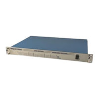
PCB Piezotronics 483C28 Installation And Operating Manual (46 pages)
SIGNAL CONDITIONER
Brand: PCB Piezotronics
|
Category: Test Equipment
|
Size: 1 MB
Table of Contents
Advertisement

PCB Piezotronics 483C28 Installation And Operating Manual (46 pages)
Brand: PCB Piezotronics
|
Category: Test Equipment
|
Size: 1 MB