Table of Contents
Advertisement
Quick Links
Advertisement
Table of Contents

Related Manuals for SpaNet Eco Cube CHP-33


Summary of Contents for SpaNet Eco Cube CHP-33
- Page 2 Safety Messages We have provided important safety messages in this manual about your heat pump. Always read and follow all safety messages. This is the safety alert symbol. It alerts you to hazards that can cause injury or harm to you and others.
-
Page 3: Safety Warnings
Safety Warnings Electrical power must be switched off before starting any work on heat pump. DO NOT attempt to modify the internal configuration of the heat pump. Read entire installation manual before use. This heat pump contains a flammable refrigerant R290. Any intervention/repairing of the refrigerant circuit is prohibited without a valid authorisation and performed by an accredited repairer. - Page 4 The heat pump should be plumbed after the spa filters and NOT before, to prevent foreign objects or debris from entering heat pump. • Spanet SV series heat pumps can only be used with Spanet SV series controllers. Eco Cube Heat Pump...
- Page 5 ADDITIONAL WARNINGS • Do not use means to accelerate the defrosting process or to clean, other than those recommended by the manufacturer. • This appliance shall be stored in a room WITHOUT continuously operating ignition sources (for example: open flames, and operating gas appliance or an operating electric heater).
-
Page 6: Table Of Contents
Table of Contents Safety Warnings ........................... 2 Table of Contents ......................... 5 Introduction .......................... 6 Specifications ........................7 Outlines & Dimensions ......................8 External Appearance ......................9 Internal Appearance ......................10 Installation Instructions ......................11 Recommended Air Flow Requirements .................... 11 Installation Location........................... -
Page 7: Introduction
1. Introduction Thank you for choosing a SpaNET SV Series Eco Cube heat pump. Air sourced heat pumps are currently the most efficient and cost-effective method of heating and maintaining the heat of your spa pool water. The SpaNET SV Series heat pump technology heats your spa water using around 75% less energy than a conventional electric heater and 50% less energy than natural gas resulting in an eco-friendly and highly cost-efficient appliance. -
Page 8: Specifications
2. Specifications CHP-33 CHP-55 ELECTRICAL Power supply 220-240V ~ 220-240V ~ Phase / Hertz 1PH / 50 Hz Electrical Connection AMP Plug Rated Current (A) ENVIRONMENTAL Operating Air Temperature C to 43 Waterproof Class IPX5 PERFORMANCE CONDITION: AIR 27 C / WATER 26 C IN 28 C OUT / HUMIDITY 80% Heating Capacity (kW) -
Page 9: Outlines & Dimensions
3. Outlines & Dimensions Dimensions Drawing (mm) Eco Cube Heat Pump... -
Page 10: External Appearance
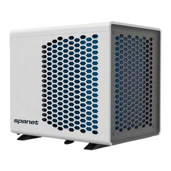
4. External Appearance Air inlets Air outlet (fan exhaust) Water inlet Water outlet Power cable entry Data cable entry Condensation drain Eco Cube Heat Pump... -
Page 11: Internal Appearance
5. Internal Appearance Condensation drain Evaporator Compressor 4-way-valve Titanium in PVC heat exchanger Water flow switch Heat exchange thermal cut out Equipotential bonding point Refrigerant fill point Ambient thermistor Compressor capacitor Circuit board 20A slow blow mains fuse Fan capacitor Mains terminal block Eco Cube Heat Pump... -
Page 12: Installation Instructions
6. Installation Instructions 6.1 Recommended Air Flow Requirements The performance and efficiency of a heat pump is directly correlated to its ability to freely draw outside ambient air through its intakes and discharge air via the exhaust fan outlet without obstruction. -
Page 13: Installation Location
6.2 Installation Location Select a suitable location in accordance with below notes and consult the local council and swimming pool safety regulations to check requirements for proximity to other equipment. • The heat pump must be located outside in a clean area where air flow will not be restricted. •... -
Page 14: Pipework Insulation
Pipework Insulation To prevent heat loss, reduce power consumption and to protect the pipes from UV exposure, it is recommended that all external pipework should be insulated with pipe lagging (example below). Condensation Drain During humid conditions, as part of the heat exchange process, the evaporator may produce a large amount of condensation runoff. -
Page 15: Installation Of Water Pipes
40mm/32mm reducing bushes (SKU: CHP-RB4032) to convert 40mm pressure pipe down to 32mm flexible pipe. These can be purchased from Spanet separately. * NOTE - Whilst it is acceptable to fit the water pipes without glue using only the hose clamps, some installers may prefer to use PVC pipe cement as well as the hose clamps for a superior long-term connection. - Page 16 Step 2: Tightly screw hose connectors onto the heat pump inlet and outlet ports as pictured below. Step 3: Use a heat gun to lightly heat the flexible pipe to make the plastic supple then push onto the hose connector taking care to push the pipe well past the O-ring*. Then seat the hose clamp at the end of the hose (ensure the clamp is positioned after the connector O-ring) and tighten securely.
-
Page 17: Connecting Water Pipes To Spa Pool
Step 4: Repeat the process in step 3 for the second pipe. 6.5.2 Connecting Water Pipes to Spa Pool Remove the spa cabinet to access the equipment bay and locate the ‘heat pump ready’ connection ports provided by your spa manufacturer (example shown in picture below). Study the plumbing to identify flow direction and connect pipes accordingly. - Page 18 Step 1: Use a heat gun to lightly heat the flexible pipe to make the plastic supple then push onto the reducing bush taking care to push the pipe well past the moulded O-ring ridge*. Then seat the hose clamp at the end of the hose (ensure clamp is positioned after O-ring ridge) and tighten securely. If you wish to use PVC pipe cement add glue after heating but before pushing pipe onto connector.
-
Page 19: Plumbing Diagram
6.6 Plumbing Diagram • Heat pump should be plumbed on the DISCHARGE side of filter pump. • Heat pump should be plumbed inline PRIOR to the spa controller wherever possible. If this is not feasible, you can plumb the heat pump Skim Filter after the spa controller, but it must be BEFORE the sanitiser. -
Page 20: Filling Spa And Bleeding Air From Pipework
6.7 Filling Spa and Bleeding Air from Pipework Spa pools are susceptible to air locks in pipework when filling with water due to the complex nature of their plumbing. The inclusion of a heat pump to the plumbing circuit adds to this complexity, increasing the risk of air locks. -
Page 21: Cable Connections
6.8 Cable Connections Data and power cables must be installed between the heat pump and spa pool in accordance with the local wiring regulations. It is best practice to separate data and power cables from each other. 6.8.1 Power Cable Connection The Eco Cube requires connection to a constant 230V power supply. - Page 22 6.8.1.1 AMP Sockets & Plugs SV series spa controllers utilise AMP mate-N-lok power connectors. The AMP connectors feature a key pattern for fail-safe one-way connection. When connecting the power cable push the plug firmly into the socket and ensure both side locking taps have been secured and latched in place. 6.8.1.2 Equipotential Bonding Point Equipotential bonding is the practise of intentionally connecting all metallic items in a zone together...
-
Page 23: Data Cable Connection
6.8.2 Data Cable Connection The Eco Cube heat pump is a slave device and is operated by an SV spa controller. It requires a data cable connection for communication between the spa controller and the heat pump itself. It is supplied with a preinstalled 5m shielded data cable ready for direct connection to an SV Series spa controller. -
Page 24: Spa Controller Heat Pump Settings
7. Spa Controller Heat Pump Settings The SV Series heat pump interface seamlessly integrates the Eco Cube heat pump for efficient heating or cooling of the spa water. There is no setup process required, the SV spa controller will automatically detect the Eco Cube on bootup, disable the electric element and take control of the heat pump operation. - Page 25 7.1.1.1 Standard Touch Pads Step 1: Simultaneously press and hold UP + DOWN buttons (to access the General Settings menu) until display shows MODE or FILT then release. Step 2: Press the UP button until display shows H.PMP (heat pump operation mode).
- Page 26 Step 4: Use the UP or DOWN buttons to toggle between AUTO / HEAT / COOL / OFF. Step 5: Press the OK button to confirm and save the setting and return to the General Settings Menu. NOTE: If there is no further button press, after 10 seconds the menu will exit and...
-
Page 27: Heat Pump With Electric Element Boost (H.ele)
Step 2: Scroll down towards bottom of General Settings menu. Step 3: Select HPMP – Heat pump operation mode. Step 4: Press on + or - button to toggle between HEAT+COOL / HEAT ONLY / COOL ONLY / DISABLED, then press SAVE, then use back arrow twice to return to home screen. -
Page 28: Adjusting Heat Pump + Electric Element Boost (H.ele)
1. If there is NO heat pump fitted to the spa, setting H.ELE = OFF does NOT disable the internal electric heating element of the SV spa control. The setting only affects the electric element operation IF a heat pump is installed. 2. - Page 29 Step 2: Press the UP button until display shows H.ELE (heat pump + electric element). Step 3: Press the OK button to enter the H.ELE setting adjustment (display will show current setting). Step 4: Use the UP or DOWN buttons to toggle between ON and OFF.
- Page 30 Step 5: Press the OK button to confirm and save the setting and return to the General Settings Menu. NOTE: If there is no further button press, after 10 seconds the menu will exit and return to default temperature display. 7.2.1.2 SmartTouch Colour Touch Screen Keypads Step 1:...
-
Page 31: Set Temperature Adjustment And Range
Step 4: Press on + or - button to toggle between ENABLED / DISABLED, then press SAVE, then use back arrow twice to return to home screen. 7.3 Set Temperature Adjustment and Range The regulation of water temperature is governed by the settings within the SV Series spa controller. The set temperature point can easily be adjusted by pressing and holding either the UP or DOWN buttons on the SV spa side touch pad fitted to your spa. -
Page 32: Winterizing Heat Pump
8. Winterizing Heat Pump In areas where freezing conditions are brief and mostly an overnight occurrence, the freeze protection of the Eco Cube and SV spa control will prevent the exchange tank and pipework from freezing by engaging the filtration pump and circulating water every hour even if sleep timers are set. Freeze protection will override any sleep or power save timers that have been set in the SV spa control. -
Page 33: Isolate Water Flow To Heat Pump (To Continue Using Spa)
8.1.2 Isolate Water Flow to Heat Pump (to continue using spa) Adjusting the valves on the spa to isolate water flow to the heat pump is only required where the heat pump is to be Winterized but the spa will continue to be used. If the whole spa is being emptied and not used during the Winter season it is not necessary to follow these steps. -
Page 34: Prepare To Restart Heat Pump After Winter
If the whole spa is being shut down for Winter, the spa side cabinet panel should be removed and couplings loosened on both the filtration pump and spa controller to completely drain pipe work of water to prevent freezing and ice damage. 8.2 Prepare to Restart Heat Pump after Winter 1. -
Page 35: Safety / Protection Systems
9. Safety / Protection Systems SV Heat pumps are equipped with the following safety protection systems: Water flow switch The heat pump is fitted with a flow switch to prevent the heat pump from operating and overheating the water in the heat exchange tank if there is insufficient or no water flow through the heat pump. -
Page 36: Maintenance
10. Maintenance The Eco Cube heat pump is a self-contained unit which, if installed as per the guidelines outlined in this manual, should provide years of trouble-free operation with next to no maintenance. 10.1 Evaporator Cleaning The evaporator does not require any special maintenance, except when it is clogged by dirt or any other debris (i.e. -
Page 37: Troubleshooting
11. Troubleshooting Should a major fault occur the SV spa controller will disable the heat pump (heating will stop) and the spa side touch pad will display a scrolling error message every 30 seconds. Refer to error codes section of this manual for further advice. However, if the spa control is not displaying any errors but the Eco Cube is not working as expected, please refer to the troubleshooting tips below. - Page 38 PROBLEM ACTION • Check SV spa controller settings. Confirm the H.PMP setting is not set to a mode which could prevent the heat pump from running. • Confirm ambient air temperature is within operational limits. • Check there is no hammer and spanner error symbol on the display. If error symbol is present, wait for the error code to scroll every 30 seconds (touch screen displays will scroll any heat pump error across the screen underneath the temperature) and take corrective action for that error accordingly.
-
Page 39: Heat Pump Error Codes
12. Heat Pump Error Codes If a heat pump fault condition is detected the standard SV touch pads will display a hammer and spanner fault icon and will scroll an error message across the LCD every 30 seconds. For SmartTouch colour touch pads the heat pump error message will continuously scroll across the display in blue writing. - Page 40 ERROR PROBLEM / ACTION • No signal from low pressure switch or insufficient refrigerant gas charge. • HEAT PUMP LOW P Check low pressure switch is securely connected to heat pump circuit board. • Check refrigerant level (if pressure gauge fitted), if low have heat pump checked by a refrigeration mechanic.
-
Page 41: Wiring Diagram
13. Wiring Diagram NOTE : This diagram is correct at the time of publication, manufacturing changes could lead to modifications. Always refer to the diagram supplied with the heat pump. Eco Cube Heat Pumps... -
Page 42: R290 Service Operations
14. R290 Service Operations This heat pump contains a flammable refrigerant R290. Any intervention on the refrigerant circuit is prohibited without a valid authorization. Before working on the refrigerant circuit, the following precautions are necessary for safe work. Only persons authorized by an accredited agency certifying their competence to handle refrigerants in compliance with sector legislation should work on refrigerant circuits. - Page 43 6. No source of flame, heat or spark It is totally forbidden to use a source of heat, flame or spark in the direct vicinity of one or more parts or pipes containing or having contained a flammable refrigerant. All sources of ignition, including smoking, must be sufficiently far from the place of installation, repair, removal and disposal, during which time a flammable refrigerant may be released into the surrounding area.
- Page 44 • that no live electrical components and wiring are exposed while charging, recovering or purging the system; • that there is continuity of earth bonding. 11. Repairs to sealed components During repairs to sealed component, all electrical supplies shall be disconnected from the equipment being worked upon prior to any removal of sealed covers, etc.
- Page 45 Electronic leak detectors shall be used to detect flammable refrigerants, but the sensitivity may not be adequate, or may need re-calibration. (Detection equipment shall be calibrated in a refrigerant- free area. Ensure that the detector is not a potential source of ignition and is suitable for the refrigerant used.
- Page 46 • Ensure that contamination of different refrigerant does not occur when using charging equipment. Hoses or lines shall be as short as possible to minimize the amount of refrigerant contained in them. • Cylinders shall be kept upright. • Ensure that the refrigeration system is earthed prior to charging the system with refrigerant. •...
- Page 47 11. Recovered refrigerant shall not be charged into another refrigeration system unless it has been cleaned and checked. 19. Labelling Equipment shall be labelled stating that it has been de-commissioned and emptied of refrigerant. The label shall be dated and signed. Ensure that there are labels on the equipment stating the equipment contains flammable refrigerant.
-
Page 48: Contact Us
Contact Us Spa Net Pty Ltd Unit 1 103 Mulgrave Road Mulgrave NSW 2756 Australia P | +61 2 4587 7766 service@spanet.com.au Eco Cube Heat Pump...
Need help?
Do you have a question about the Eco Cube CHP-33 and is the answer not in the manual?
Questions and answers