
Related Manuals for SpaNet SHP-60P


Summary of Contents for SpaNet SHP-60P
- Page 1 Directions for installation and maintenance SHP-60P SHP-80P SHP-100P SHP-120P SHP-140P SHP-170P SHP-190P...
-
Page 2: Table Of Contents
Contents 1. Introduction ………………….…………………………….……..…………. 2. Caution …………………………………………………….………………….….. 3. Delivery control …………………………………………......4. Technical description …………………………….…………………….. Technical characteristics Outside Inside explored view Wire control operation General diagram of the refrigerating circuit Safety and control systems 5. Installation ……………………….…………………………………..Rules of installation Hydraulic connections Electric connections 6. -
Page 3: Introduction
1- Introduction We thank you for having chosen our Heat pump. This installation and maintenance notice contains the necessary information to its installation (delivery control, the installation, the connections) and to its repair. It is a complementary document to the user’s manual which describes its instructions for use. -
Page 4: Technical Description
At the delivery time, check the condition of packing; in case of damages, have reservation about them to the carrier, before 48 hours and by registered letter with acknowledged receipt. Before any manipulation, check the complete state of the machine. Technical description Characteristics: MODEL SHP-60P SHP-80P SHP-100P SHP-120P SHP-140P SHP-170P SHP-190P... -
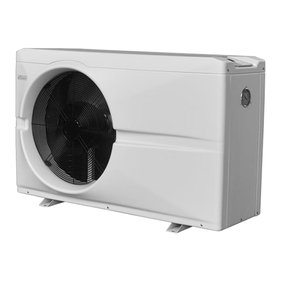
Page 5: Outside
Outside: Fan protection net Front panel Control panel Refrigerant pressure manometer Connection for water outlet Wire connection for power supply Connection for water intlet Rear net Inside: (Front sheet cover and panel removed) Evaporator Compressor High and low pressure interruptor Titanium heat exchanger Temperature sensor of swimming pool water Four way valve... -
Page 7: Wire Control Operation
Wire control operation The function of the LCD display and control: Set the operation parameter: ◎ Standby status-press “SET” button 5 seconds to enter operation parameter setting interface. ◎ Press " " or " " to check parameter(parameter from 0-P, see Operation Parameter Table). - Page 8 Choose the operation mode: ◎ Press “ ” to power on unit. Under running, the LED displays the water temperature. ◎ Press “ ” to choose mode(mode can be changed under running) ◎ Press “ ” to set temperature 1 press “...
-
Page 9: Setting The Time
Check current temperature: ◎Under running, press “SET” button 5 seconds and “ ” or “ ” to check the current status of the unit. You can check Water Temp-/Compressor protection exhaust Temp-/Heat Copper Temp-/Return Gas Temp-/Ambient Temp-/Cooling Copper Temp-/ Actual open steps of EE valve. -
Page 10: General Diagram Of The Refrigerating Circuit
General diagram of the refrigerating circuit The heat pump is reversible allowing the swimming-pool’s heating or cooling: Swimming-pool water’s heating mode: The cold and liquid refrigerant fluid absorbs the heat contained in the air through the evaporator (gilled radiator), in which it is vaporizing; it is then put up in pressure and in temperature by the compressor which sends it in the condenser (exchanger) where it loses its heat (in giving it to the water of swimming pool) and comes back in liquid state;... - Page 11 Swimming-pool water’s cooling mode: The 4 way valve reverses the circulation of the refrigerant fluid; the fluid vaporizes in the exchanger (evaporator) in getting the heat of the water, goes through in the compressor which reheats it and through in the gilled radiator (which becomes condenser) where it comes back to liquid state. Cold air Evaporator (gilled...
-
Page 12: Safety And Control Systems
Safety and control systems Heat pumps are equipped with the following standard protection systems: 1. Water flow switch Thanks to this flow switch, the heat pump will not work when the filter pump is not working (and the water is not circulating). This system prevents the heat pump from heating only the water flow in the heat pump itself. - Page 13 5. Anti-frost protection during winter This protection can only be activated if the heat pump is in STAND-BY mode. 5.1 First anti-frost protection If the filter pump is controlled by the heat pump (regardless of the value for parameter 9) and when the water temperature lies between 2 and 4 °...
-
Page 14: Installation
5- Installation Rules of installation: Electric and hydraulic connections must be carried out according to standards in effect (NF C 15 100, CE I 364). The machine must be installed outside. The machine must be posed on its ant vibratory studs, set and lying flat and on a massive base (concrete slab);... -
Page 16: Electric Connections
Electric connections: CAUTION: before connecting the machine, make sure that the feeder is disconnected to the electrical network. The electric installation must be carried out by an experienced electrician and the supply must come from a severing equipment and differential protection; the whole must be carried out according to standards' in force in the country where the material is installed. -
Page 17: Water Flow And Refrigerating Circuit Pressure
6- Water Flow and refrigerating circuit pressure After putting into service, do the settings of pressure of the refrigerant circuit for having an optimal operating of the heat pump, following: Stage 1: Before starting the Heat Pump, ambient temperature around 20° C, refrigerant meter shows pressure from 14 to 16kg/cm²... -
Page 18: Environment Problem
7 – Environment problem Under certain external conditions the heat exchanges between the refrigerant and the water on one hand and between the fluid and the air on the other hand are insufficient; the consequence is that the refrigerating circuit runs up in pressure and the compressor consumes more electricity. -
Page 19: Maintenance And Inspection
8. Maintenance and inspection 8.1 Maintenance Check the water inlet and drainage often. The water and air inflow into the system should be sufficient so that its performance and reliability does not get compromised. You should clean the pool filter regularly to avoid damage to the unit caused by clogging of the filter. -
Page 20: Overview Of Possible Error Codes Displayed On The Screen
8.3 Overview of possible error codes displayed on the screen Go back to chapter 4 “Protection systems” for more detailed information. The heat pump screen displays one of the following codes: Display Problem Cause Solution “WATER IN” sensor out PP 1 Sensor open or short-circuited Check or replace the sensor of order... - Page 21 9.Electrical diagrams...
Need help?
Do you have a question about the SHP-60P and is the answer not in the manual?
Questions and answers