Table of Contents
Advertisement
Quick Links
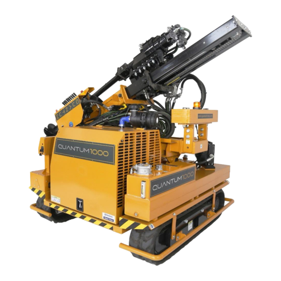
Instruction Safety Manual
Quantum Pile Driver
Pre - Caution:
•
To work with this machine, operators must read and fully understand this
instruction manual. They must be well trained in the use of this machine.
•
All safety controls must be in place before startup.
•
Operators and owners must read this manual and other supporting material
provided by the Manufacturer.
This manual provides best practices for operating and maintaining your Quantum Pile
Driver
800 /1000/1200
Advertisement
Table of Contents


Need help?
Do you have a question about the 800 and is the answer not in the manual?
Questions and answers