
Related Manuals for AMERLIFE 1061110256A


Summary of Contents for AMERLIFE 1061110256A
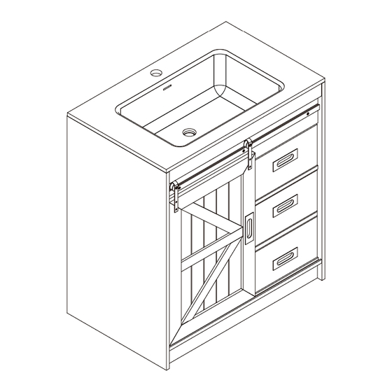
- Page 1 CABINET Assembly Instructions 1061110256A - Please keep for future reference 1061110257A 1061110258A Dimensions Width - 31.1inch Depth - 19.5inch Height - 33.5inch Important – Please read these instructions fully before starting assembly Issue 1 - 09/01/2024...
-
Page 2: Handy Hints
Safety and Care Advice Important – Please read these instructions fully before starting assembly • Check you have all the • During assembly do not stand • To reduce components and tools listed on or put weight on the product, the likelihood of the following pages. - Page 3 Components - Fittings Note: may be supplied than are required. Cam Bolt x 26 Cam Lock x 26 Wooden Dowel x 21 3.5*14mm Screw x 24 5*40mm Screw x 12 4*14mm Screw x 4 6*30mm Bolt x 3 Wall Fixing Pack x 2 Allen Key x 1 Pulley x 2 Screw and plastic cap x 2...
- Page 4 DO NOT OVER TIGHTEN. NE PAS SERRER EXCESSIVEMENT.
- Page 5 Components - Panels Please check you have all the panels listed below (39 x 58 x 1.5cm) x1 (49.4 x 76 x 1.5cm) x1 (49.5 x 85 x 1.5cm) x1 (7.5 x 76 x 1.5cm) x1 (75.6 x 2.5 x1.5cm) x1 (18 x 76 x 3.3cm) x1 (7.5 x 76 x 1.5cm) x1 (7.5 x 32.8 x1.5cm) x2...
- Page 6 Components - Panels Please check you have all the panels listed below (14 x 33 x 1.2cm) x1 (42.8 x 63 x 1.5cm) x1 (14 x 27.9 x 1.2cm) x1 (17.5 x 32.2 x 1.5cm) x1...
- Page 7 Assembly Instructions...
- Page 8 Assembly Instructions Step 1 D x 12 M x 2 Use screw (D) to secure slide track (CL) to part (1) with a screwdriver. Use screw (D) to secure slide track (CR) to part (2) with a screwdriver.
- Page 9 Assembly Instructions Step 2 C x 7 Insert wooden dowel (C) into part (3, 4). Step 3 E x 2 Attach part (3) to part (4) using screw (E) with a screwdriver.
- Page 10 Assembly Instructions Step 4 A x 2 C x 2 CAM-LOCK Tighten until shoulder is flush with panel.Do not overtighten Shoulder or undertighten(see example below) NO GAP Panel Panel Attach cam bolt (A) to part (1) with a screwdriver. Insert wooden dowel (C) into part (1). Step 5 E x 2 Attach part (1) to part (4) using screw (E) with a screwdriver.
- Page 11 Assembly Instructions Step 6 A x 9 CAM-LOCK Tighten until shoulder is flush with panel.Do not overtighten Shoulder or undertighten(see example below) NO GAP Panel Panel Attach cam bolt (A) to part (2) with a screwdriver. Step 7 C x 4 ×...
- Page 12 Assembly Instructions Step 8 B x 2 Attach part (5) to part (2), then insert and secure cam lock (B) to part (5) to lock it. Step 9 B x 5 Attach part (1) to part (5), then insert and secure cam lock (B) to part (5) to lock it. Attach part (3, 4) to part (2), then insert and secure cam lock (B) to part (3, 4) to lock it.
- Page 13 Assembly Instructions Step 10 G x 3 H x 1 Countersunk Hole Attach part (6) to part (7) using bolt (G) with allen key (H). Step 11 C x 8 Insert wooden dowel (C) into part (7, 8, 9).
- Page 14 Assembly Instructions Step 12 B x 2 Attach part (7) to part (2), then insert and secure cam lock (B) to part (7) to lock it. Step 13 Countersunk Hole B x 2 Attach part (8, 9) to part (2), then insert and secure cam lock (B) to part (8, 9) to lock it.
- Page 15 Assembly Instructions Step 14 CAM-LOCK A x 7 Tighten until shoulder is flush with panel.Do not overtighten Shoulder or undertighten(see example below) NO GAP Panel Panel Attach cam bolt (A) to part (10) with a screwdriver. Step 15 B x 7 Attach part (10) to part (3, 4, 7, 8, 9), then insert and secure cam lock (B) to part (3, 4, 7, 8, 9) to lock it.
- Page 16 Assembly Instructions Step 16 J x 4 Insert protective foot (J) into part (2, 10). Step 17 K x 2 Attach screw and plastic cap (K) to part (20) with a screwdriver.
- Page 17 Assembly Instructions Step 18 Place door (20) on the track. Step 19 F x 4 L x 2 Door adjustment: a. to adjust door, loosen screws shown and move door to suit b. retighten screws Place pulley (L) on the bar, and then attach pulley (L)to door (20) using screw (F) with a screwdriver.
- Page 18 Assembly Instructions Step 20 I x 2 Secure vanity to the wall by using appropriate wall plus and screw(I). Step 21 Apply a thin layer of silicone sealant around the top of the vanity, and then carefully secure the sink in place.Remove excess silicone sealant with a damp rag.
- Page 19 Assembly Instructions Step 22 E x 4 Attach part (11, 12) to part (13) using screw (E) with a screwdriver. Slide part (14) into grooves. Step 23 Step 23-1 Step 23-2 CAM-LOCK A x 4 B x 4 Tighten until shoulder is flush with panel.Do not overtighten Shoulder or undertighten(see example below)
- Page 20 Assembly Instructions Step 24 D x 6 DL x 1 DR x 1 Use screw (D) to secure slide runner (DL) to part (11) and slide runner (DR) to part (12) with a screwdriver. Step 25 E x 4 Attach part (16, 17) to part (18) using screw (E) with a screwdriver. Slide part (14) into grooves.
- Page 21 Assembly Instructions Step 26 A x 4 B x 4 CAM-LOCK Step 26-1 Step 26-2 Tighten until shoulder is flush with panel.Do not overtighten Shoulder or undertighten(see example below) NO GAP Panel Panel 26-1: Attach cam bolt (A) to part (19) with a screwdriver. 26-2: Attach part (19) to part (16, 17), then insert and secure cam lock (B) to part (16, 17) to lock it.
- Page 22 Assembly Instructions Step 28 last step.
Need help?
Do you have a question about the 1061110256A and is the answer not in the manual?
Questions and answers