
Related Manuals for Model Train Technology D-Signal Controller


Summary of Contents for Model Train Technology D-Signal Controller
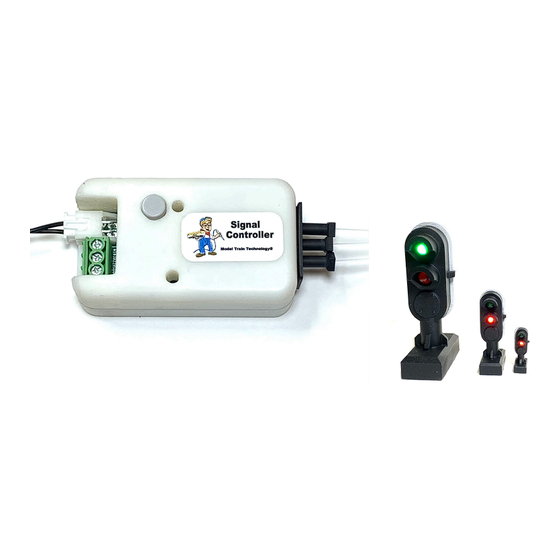
- Page 1 D-Signal Controller™ OPERATIONS MANUAL LED and Fiber Version Version 2.0a April 2023...
- Page 2 April 2023...
- Page 3 INTRODUCTION The Model Train Technology™ D-Signal Controller™ provides an extremely simple but powerful plug-and-play system for lighting and animating ground-based signals, otherwise known as “dwarf” signals. These signals are mostly used in connection with turnouts so you will find them in abundance in freight and switching yards.
- Page 4 5. Mechanical toggle switch ** requires the MTT coil sensor. Additional features of the D-Controller are: 1. Remembers the turnout state when power is turned off. 2. The lights can fade or change instantly. 3. The brightness of each output can be set independently 4.
- Page 5 Controller. No software, computer or programming is necessary. And there is no complicated wiring. You don’t need DCC to run the D-Signal Controller but it’s there if you want it. When one of the two D-Controller inputs is tripped by any one of the methods listed above, the light pair associated with that input switches Off/On.
- Page 6 fiber CTC panel light as one of the fibers with the MTT 2-core pin. See the diagram below for the display example. The two inputs normally work independently. You can use our 2-core fiber pins and connect two dwarfs to each light. In this way you can have lights facing in both directions that work in tandem.
-
Page 7: Setup And Operation
SETUP AND OPERATION When you plug in power the blue internal LED will light. The CLOSED or green side of each FIBER output will light. The D-Controller setup is simple. Connect to a 5 to 12VDC power source (or DCC power) to the topmost JST terminals as shown above. The JST connector with wire is included. -
Page 8: Summary Of Settings
If you use our MTT Power Module to power your detectors and the D- Controller you only need the single yellow SIGNAL wire to connect the trigger wire. If you are connecting many signals to the Power Module we recommend the 12V version. If you have another kind of sensor system you can either have them share the same power supply or use the GROUND terminal. - Page 9 Pressing the gray SELECT button on the top of the D-Controller will activate settings according to this chart: SETTING THE BIGHTNESS April 2023...
- Page 10 Setting the brightness for each output is accomplished by selecting the number of the output you want to adjust via the SELECT button. You press the select button 1, 2, 3, or 4 times to select any light 1 through 4. Within one second of button release, all the lights will go out and the selected light will light.
- Page 11 The above chart indicates that 5 presses of the SELECT button will switch the D-Controller into Fade mode. Pressing 6 times will turn Fade mode OFF. RESETTING THE D-CONTROLLER If you happen to get lost while configuring the D-Controller or want to get everything back to its default settings use the reset procedure.
- Page 12 Depending on your DCC system, the DCC hand control might show the last known turnout position. Or it might not. But the MTT D-Controller saves each turnout command so that when you turn OFF the power to your entire layout and then turn it back on, the D-Controller will show the lights in the correct and last position of the turnout! To coordinate the DCC setting with your D-Controller, you set the D-...
- Page 13 In wired, non-interlock mode, the D-Controller uses the THROWN direction as a tripped condition. If you find that the Thrown and Closed states are backward to the way you want to display the signal, simply reverse the fiber cable connections to the D-Controller. To operate the D-Controller with DCC you must power and connect your DCC rails A &...
- Page 14 To set a new address, select the Accessory/Turnout number that you want to assign on your DCC hand cab. This can be a number from 1- 2044. Using your DCC hand cab, enter that number and then press the appropriate command to set a CLOSED or THROWN switch event. In NON-interlink mode, either closed or thrown will work.
- Page 15 INTERLOCKING & THREE-WAY SWITCHES YouTube Videos: https://youtu.be/Dk7eP6yPSQg https://youtu.be/a3hHoweTQF0 https://youtu.be/ILXS3EbvSjA Interlocking, as used here, is the process of connecting the output of one D-Controller/turnout to the Input of a following D- Controller/turnout. When turnout #1 is closed, turnout#2 is effectively cut off from the mainline and thus both of its sides of turnout #2 should show a RED indication.
- Page 16 However, with interlocking you can cascade your D-Controllers and signals through the entire yard, both entrances and exits. If you are using DCC you do not have to wire anything – just connect the A/B rail power to the D-controller, set it’s address and configure it accordingly. If you are connecting the D-Controller via one of the wired methods, the process is almost as easy.
- Page 17 mainline. To establish a multi-tier or cascading branch of turnouts, use a simple switching diode on the input side of the D-Controller so that each branch of the tree can separately trigger the interlocking. The figure below shows this configuration. April 2023...
- Page 18 THREE WAY SWITCHES The D-Controller can synchronize with all three-way switches. Since a three-way switch requires two turnout machines, likewise you will need two D-Controllers to make this work. Here is the basic layout of three-way signaling. Note that only one of the light outputs of D-Controller Primary is needed.
- Page 19 DCC CASCADING INTERLOCKING While at first this might seem daunting, the architecture is very simple and easy to implement. In short, 1. For each turnout on your layout, assign a D-Controller and give it the same address that you use to switch the turnout. We call this mirroring.
- Page 20 April 2023...
- Page 21 HOW TO LOAD INTERLOCKING DCC ADDRESSES. You should have already practiced setting the D-Controller’s own DCC address. The process for loading the interlocking address is similar. 1. Using the included table, mark down the address numbers of each interlocking turnout AND, mark down which way you chose for the clear path to the exit, either Thrown or Closed.
- Page 22 8. To finish and EXIT this mode, press the Select button once. 9. The D-Controller will return to ready mode. It’s not possible to edit an individual address or setting. The only way to fix an error is to clear the interlocking address and start again. I have a test layout that has 6 switches.
-
Page 23: Limitation Of Liability
ELECTRONICS AND STATIC ELECTRICITY The MTT PRECISION DETECTOR™ - Trackside circuit board and components are exposed when the cover is off. Electricity can be dangerous. Static electricity can cause component failure. Scuffing along a carpet and then touching one of the component connectors can cause a static spark. - Page 24 Model Train Technology LLC 10524 Moss park Rd. Ste. 204-256 Orlando, Florida 32832 407-242-5436 www.ModelTrainTechnology.com support@modeltraintechnology.com Version 2.0a Copyright© 2023 Model Train Technology LLC April 2023...
Need help?
Do you have a question about the D-Signal Controller and is the answer not in the manual?
Questions and answers