Advertisement
Advertisement
Table of Contents

Related Manuals for Model Train Technology S-Signal Controller


Summary of Contents for Model Train Technology S-Signal Controller
- Page 1 S-Signal Controller™ OPERATIONS MANUAL RGY SEARCHLIGHT Version 1.3a April 2024...
- Page 2 April 2024...
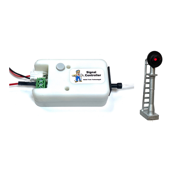
- Page 3 INTRODUCTION The Model Train Technology™ S-Signal Controller™ (Searchlight) provides an extremely simple plug-and-play system for lighting and animating layout SEARCHLIGHT-style block signals that have a single light. This version of the controller is only available in Fiber Cable lighting to match with the fiber searchlight block signal.
- Page 4 OVERVIEW Each MTT S-Signal Controller (“Controller”) is a pair of single light 3-color output controller that stands on its own and is triggered by a sensor, mounted either under or on the side of the track. Our Precision Detector™ is a great choice since it is not based on typical IR (infrared) and is therefore not impacted by difficult lighting conditions.
- Page 5 The Controller has two outputs that are synchronized. You can individually adjust the different colors, and this will affect both outputs. We use a single RGY LED to light both outputs. The colors of the LEDS (Red, Yellow and Green) do not glow at the same brightness with the same voltage.
-
Page 6: Fade Mode
BLUE LIGHT TIMEOUT If set, the BLUE indicator light will go out after 60 seconds of startup or if the Select button is not pushed. Each time you press the Select button, the light will come back on and start its 60 second timeout clock. -
Page 7: Connecting Power
push of the switch changes the aspect from Green, to Red, to Yellow and back to Green. Push the SELECT button 8 times to activate STEP mode. Press SELECT 8 times again to turn it off. When the change turns the option ON, the lights will flash 4 times. - Page 8 LATCHING (Clear-to-Proceed) While not a true CTC signaling system, there is one feature that will give the appearance of one – without the complexity. In short, if you connect the Signal wire of the Signal controller from the block ahead to the LATCH terminal of the Signal Controller of the block behind, while the block ahead is occupied the block behind will wait at the last aspect before green.
- Page 9 April 2024...
-
Page 10: Setup And Operation
SETUP AND OPERATION HO Scale: Simply plug the fiber into the Controller Manifold hole (no pin required) N Scale: Use the included Fiber pin – insert the cable into the pin and insert the pin into the Controller manifold. When you plug in power the blue internal LED will light. The LED output light will be green. - Page 11 Connect your Signal LEDs as shown below. USE ONLY 12VDC (5v has been obsoleted) The Detect Signal input is an OPEN DRAIN (GROUND) connection. That means that the signal it’s looking for is a digital LOW. NOTE: this Open Drain low is NOT the same as a LOW/HIGH from an Arduino.
- Page 12 GROUND will trip the Controller. This is how manual GROUND THROWN turnout switches will be connected. Very simple. SELECTING A SIGNAL BEHAVIOR (ASPECTS) You push the Select Pushbutton the number times needed to select an option according to the table below. Once you stop pushing the button the Controller will wait 2 seconds and then all the LEDs will turn off.
- Page 13 SETTING THE BIGHTNESS (LED OR FIBER) Setting the brightness for each color is accomplished by selecting that color with the SELECT pushbutton To adjust each light color, press the button X number of times as follows: GREEN YELLOW For example, to change the brightness of Green, press the SELECT button once.
- Page 14 April 2024...
- Page 15 DCC OPERATIONS April 2024...
- Page 16 The Controller can respond DCC Accessory messages just like your turnout controllers. You can set the Controller to the SAME address as a turnout so that when you change the turnout, the Controller automatically changes the color of the signal. You can also configure several Controllers to the same switch address so that multiple but different signal lights will light according to your layout design.
- Page 17 To operate the Controller with DCC you must power and connect your DCC rails A & B to the Controller. For small and medium sized layouts this should not be a problem since the Controller and LED require about 30ma each to run. For larger layouts or layouts with a lot of signals connected to you DCC track we suggest you create a separate Booster zone.
- Page 18 As soon as you select CLOSED or THROWN, the Controller will flash 4 times and the lights will go off. The Controller is now set to the new address. Lastly, the Controller will enter the unoccupied/un-triggered state which usually means that the green light will go on. While DCC is connected and active, DCC commands will override the input signal and latching functions.
- Page 19 Signal Controller Magnetic Bracket (Available for order) April 2024...
- Page 20 ELECTRONICS AND STATIC ELECTRICITY The MTT PRECISION DETECTOR™ - Trackside circuit board and components are exposed when the cover is off. Electricity can be dangerous. Static electricity can cause component failure. Scuffing along a carpet and then touching one of the component connectors can cause a static spark.
-
Page 21: Limitation Of Liability
LIMITATION OF LIABILITY UNDER NO CIRCUMSTANCE SHALL COMPANY OR ITS AFFILIATES, PARTNERS, SUPPLIERS OR LICENSORS BE LIABLE FOR ANY INDIRECT, INCIDENTAL, CONSEQUENCIAL, SPECIAL OR EXEMPLARY DAMAGES ARRISING OUT OF OR IN CONNECTION WITH YOUR USE, OR INABILITY TO USE THE PRODUCT, WHETHER OR NOT THE DAMAGES WERE FORESEEABLE AND WHETHER OR NOT COMPANY WAS ADVISED OF THE POSSIBLITY OF SUCH DAMAGES. - Page 22 April 2024...
- Page 23 April 2024...
- Page 24 Model Train Technology LLC 10524 Moss park Rd. Ste. 204-256 Orlando, Florida 32832 407-242-5436 www.ModelTrainTechnology.com support@modeltraintechnology.com Version 1.3a(S) Copyright© 2021 Model Train Technology LLC April 2024...
Need help?
Do you have a question about the S-Signal Controller and is the answer not in the manual?
Questions and answers