Advertisement
Quick Links
Advertisement

Related Manuals for Model Train Technology G-Controller


Summary of Contents for Model Train Technology G-Controller
- Page 1 G-Controller™ OPERATIONS MANUAL Version 1.1a June 2022...
- Page 2 June 2022...
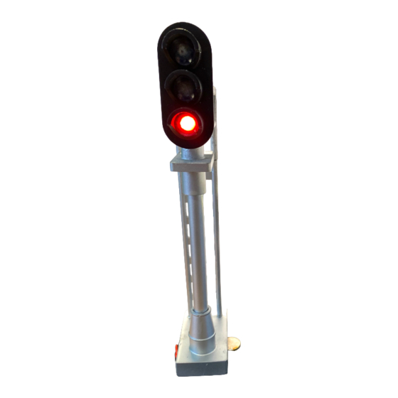
- Page 3 INTRODUCTION Video Instructions: https://youtu.be/FRAdZwGpwZQ The Model Train Technology™ G-Controller™ provides an extremely simple plug-and-play system for lighting and animating G Scale block signals and RR Crossing Flashers. • No Soldering • No Computer • No Programming Our simplified system will provide great animation in just a...
- Page 4 OVERVIEW Each MTT G-Controller (“Controller”) stands on its own and is triggered by a Precision Detector MAX™ sensor, mounted either on the front or back of the main circuit board depending on whether you have the battery or wired 12VDC version.
- Page 5 The Controller has four outputs that are synchronized to the selected aspect behavior. You can adjust the brightness of each of the outputs individually. This lets you set the brightness appropriate to your layout. You can also individually adjust each of the different colored LEDS. The typical colors of the LEDS (Red, Yellow and Green) do not glow at the same brightness with the same voltage.
- Page 6 • R, R&Y, G&Y, Green • R, R&Y, R&Y-Flash, G&Y-flash, Green • Red, fade to Yellow, fade to Green • Alternate flash Red & Green (speed adjustable) * • Alternate flash R & G with fade (speed adjustable) * *For use with gate crossings There are two types of controllers: 1.
- Page 7 While not a true CTC signaling system, there is one feature that will give the appearance of one – without the complexity. In short, if you connect the Signal wire of the G-Controller from the block ahead to the LATCH terminal of the G-...
- Page 8 G-Controller Circuit Board Blue SENSOR Indicator P2 -Sensor Timeout & P3 -Detect Range Brightness adjustment adjustment P1 - Aspect Changing Speed adjustment Select Button Signal Out Ground/Common Battery ON/Off Latch IN terminal Detect IN terminal YELLOW LED output GREEN voltage Jumper...
-
Page 9: Setup And Operation
SETUP AND OPERATION lide the battery power switch into the If battery powered, s UP/ON position. Otherwise, activate your 12VDC supply. After 1 second the blue indicator LED will flash four times rapidly and the green LED will light. If you put your hand or an object in front of the sensor, the blue LED will light, and the Controller will change the aspect to RED (Occupied). - Page 10 the Controller is released after the train passes. For example, the train could pass, and the controller might wait 20 seconds (stay RED) until it starts the aspect timer. This helps to increase realism of the signal changes. Another reason to use the time out adjustment is to AVOID the sensor going off when it sees a gap between train cars.
- Page 11 Controller reads the setting at the beginning of each detector trip event. FORWARD LATCHING The way standard latching works is the G-Controller in the forward block “holds” the G-Controller behind it at the YELLOW stage until the train is clear of the forward block. Once clear the train is clear of the forward block, it releases the latch and the block behind it is cleared to Green.
- Page 12 This also means that the blocks have been tripped by detection. Forward Latching allows a G-Controller (via Detection) to cause a “Non-tripped” G-Controller to instantly show Yellow. This would normally be caused by two trains approaching each other with a passing siding nearby.
- Page 13 June 2022...
- Page 14 RESET To reset the Controller to factory defaults, press the SELECT button 13 times. SETTING THE RANGE TO STANDARD MODE By default, the sensor is set to detect the range from 10mm to 600mm. If you happen to have set the range to ZONE mode, press the SELECT button 11 times to return to STANDARD MODE.
- Page 15 SETTING THE RANGE TO ZONE MODE To avoid objects, people, cats, lizards (?) from accidentally tripping the sensor there is ZONE mode. ZONE mode is a 70mm wide detection zone that can be positioned anywhere within the max range of 600mm. To set the detector into ZONE mode press the SELECT button 12 times.
- Page 16 AUTOMATIC RANGE CALIBRATION The Precision Detector includes a feature called Auto Calibrate. This make setting the exact distance for detection to a rail car extremely simple. STEPS: 1. To activate the saved calibration, the trim pot for ranging must be set to zero. Turn the trim pot with the screwdriver all the way to the left (counterclockwise).
- Page 17 5. The LED will THEN blink 10 more times, once per second, to allow you time to place a train car on the track in front of the sensor you wish to calibrate. 6. After 10 seconds (10 blinks) there will be a 1 second pause and then the LED will blink very rapidly for about 1 second.
-
Page 18: Configuration Mode Options
Calibrate value is used and the trim pot is ignored. When the trim pot is non-zero, the setting of the trim pot is used. TRIGGER TIMEOUT SETTINGS Rotate the P1 trim pot clockwise to increase the length of the detector timeout up to 30 seconds. CONFIGURATION MODE OPTIONS For the following setting you will need to enter the Controller’s configuration mode. - Page 19 3. The Controller is now in CONFIGURATION MODE. SETTING THE LED BIGHTNESS Setting the brightness for each output is accomplished through a series of pushes to the select button. In CONFIGURATION MODE, press the select button the number of times according to this chart for the LED you wish to adjust: YELLOW 4 GREEN...
- Page 20 Gently Insert the screwdriver into the P2 adjustment screw hole and turn the insider screw clockwise and counter clockwise to reach the desired brightness for the red LED. When you turn the P2 trimPot, the blue LED will flicker. This lets you know that something is happening.
- Page 21 (red and green). SEVEN LIGHT SIGNALS The G-Controller has four outputs, the fourth output is used to light the center light on a round 7 light signal. We currently support two behaviors: Pennsylvania Railroad (PRR) and Long Island Railroad (LIRR).
- Page 22 For the LIRR the signals will look like this: NOTE: typically, the PRR STOP is two Reds horizontal with the middle light off. There are some variations, but this is what this controller will show. If you want green and yellow signals, we can do that.
-
Page 23: Sleep Mode
- PRR, no center light with RED. - LIRR, center light on all the time If you have a three light signal this will have no effect on operations. SLEEP MODE To extend battery life, you can set the Controller into SLEEP mode. - Page 24 SIGNAL OUT /DETECT TERMINAL The Controller has a SIGNAL OUT terminal that can be used to trigger a variety of actions: 1. Act as a trip signal for Latching 2. Trip the Sound Module for Crossing Bell 3. Trip our Relay Adapter/Relay for other Animations This is the same as if a separate Precision Detector was placed on the layout –...
- Page 25 June 2022...
- Page 26 ELECTRONICS AND STATIC ELECTRICITY The MTT PRECISION DETECTOR™ - Trackside circuit board and components are exposed when the cover is off. Electricity can be dangerous. Static electricity can cause component failure. Scuffing along a carpet and then touching one of the component connectors can cause a static spark.
-
Page 27: Limitation Of Liability
LIMITATION OF LIABILITY UNDER NO CIRCUMSTANCE SHALL COMPANY OR ITS AFFILIATES, PARTNERS, SUPPLIERS OR LICENSORS BE LIABLE FOR ANY INDIRECT, INCIDENTAL, CONSEQUENCIAL, SPECIAL OR EXEMPLARY DAMAGES ARRISING OUT OF OR IN CONNECTION WITH YOUR USE, OR INABILITY TO USE THE PRODUCT, WHETHER OR NOT THE DAMAGES WERE FORESEEABLE AND WHETHER OR NOT COMPANY WAS ADVISED OF THE POSSIBLITY OF SUCH DAMAGES. - Page 28 Model Train Technology LLC 10524 Moss park Rd. Ste. 204-256 Orlando, Florida 32832 407-242-5436 www.ModelTrainTechnology.com support@modeltraintechnology.com Version 1.1a Copyright© 2022 Model Train Technology LLC June 2022...
Need help?
Do you have a question about the G-Controller and is the answer not in the manual?
Questions and answers