Table of Contents
Advertisement
Quick Links
SIP Industrial Products Limited
Gelders Hall Road
Shepshed
Loughborough
Leicestershire
LE12 9NH
United Kingdom
For help or advice please contact
your distributor, or sip directly
on:
Tel.: 01509 500400
Email:
sales@sip-group.com
or
customerservice@sip-group.com
www.sip-group.com
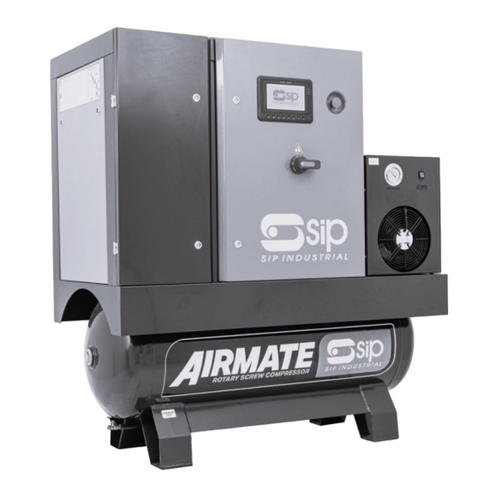
SIP Variable Speed Direct Drive Rotary
Screw Compressors
With Dryer and Filter
SIP Codes 08264 to 08281
Please read and fully understand the instructions in this manual
before operation. Keep this manual safe for future reference.
1
Advertisement
Table of Contents

Subscribe to Our Youtube Channel
Related Manuals for SIP VSDD Series


Summary of Contents for SIP VSDD Series
- Page 1 SIP Industrial Products Limited Gelders Hall Road Shepshed Loughborough Leicestershire SIP Variable Speed Direct Drive Rotary LE12 9NH Screw Compressors United Kingdom With Dryer and Filter For help or advice please contact your distributor, or sip directly SIP Codes 08264 to 08281 Tel.: 01509 500400...
- Page 3 INDEX Description Page Introduction Safety Symbols Used Throughout This Manual Safety Instructions 6 - 9 Electrical Connection 10 - 11 Technical Specification Getting To Know Your VSDD Compressor 13 - 17 Guarantee Installation 19 - 21 Operating Instruction 22 - 28 Maintenance 29 - 30 Troubleshooting...
- Page 4 INTRODUCTION Thank you very much for choosing and using the SIP Industrial Products se- ries of Variable Speed Direct Drive Screw Compressors. Please read the user's manual carefully before operating the machine. The SIP VSDD series of screw compressors are a Rotary Screw design.
-
Page 5: Safety Symbols Used Throughout This Manual
SAFETY SYMBOLS USED THROUGHOUT THIS MANUAL Note: Supplementary information. Danger / Caution: Indicates risk of personal injury and/or the possibility of damage. Warning: Risk of electrical injury or damage! CAUTION: The warnings and cautions mentioned in this user manual can not cover all possible conditions and situations that may occur. -
Page 6: Safety Instructions
SAFETY INSTRUCTIONS Make sure that mains voltage corresponds to the voltage indicated on rating plate and that cable of suitable cross-section are used for electric connec- tions. Always check oil level before starting the compressor. Be familiar with emergency stop control and all other controls. Unplug / disconnect from the mains supply before any maintenance work, to avoid accidental start. - Page 7 SAFETY INSTRUCTIONS...Cont code and serial number indicated on rating plate. Always follow the maintenance schedule specified in the user’s guide. Do not touch inner parts and pipes as they are very hot during compressor operation and stay hot for a certain time after the compressor stops. Do not position flammable parts / chemicals close to and onto the compres- sor.
- Page 8 SAFETY INSTRUCTIONS...Cont Compressed air is dangerous. Do not point the jet of air at persons or animals and do not discharge compressed air against the skin. DO NOT operate your compressor with any protection guard re- moved. Repairs must only be carried out by a qualified engineer. If problems occur, contact your dealer.
- Page 9 SAFETY INSTRUCTIONS...Cont vent all pressurised air from within the tank and other equipment attached to it. Make sure that children and animals are kept well away from the compressor and any equipment attached to it. Make sure that all individuals using the compressor have had the necessary training and have read and fully understand these oper- ating instructions.
-
Page 10: Electrical Connection
ELECTRICAL CONNECTION WARNING: Read these electrical safety instructions thoroughly before connecting the product to the mains supply. This compressor is for use with a 400V three phase industrial supply and should be grounded/earthed. Make sure that the product is connected to an outlet with the correct rating. - Page 11 ELECTRICAL CONNECTION...Cont Fig.1 Fig.1 Insulation Cover Mains Supply Isolator Switch Earth / Ground Connection Fig.2 Fig.2 Connect the mains input cable to terminals L1, L2, L3...
-
Page 12: Technical Specification
TECHNICAL SPECIFICATION Model 08271 & 08272 08276 08273 08281 08280 Mains Supply 400v 32A 400v 32A 400v 32A 400v 64A 400v 64A Rated Power 7.5KW 14KW 14KW 18KW 18KW Motor Power - IE4 5.5KW 11KW 11KW 15KW 15KW Receiver 200L 500L 500L 500L... - Page 13 GETTING TO KNOW YOUR VSDD COMPRESSOR...
- Page 14 GETTING TO KNOW YOUR VSDD COMPRESSOR...Cont Item Description Item Description 200/500L Receiver Side Access Panel Front Access Panel AVM Mounting Point Mains Isolator Switch Fan Motor Emergency Stop Ball Valve 3/4” BSP Colour LCD Touch Screen Condensate Drain Rear Access Panel Item Description Item...
- Page 15 GETTING TO KNOW YOUR VSDD COMPRESSOR...Cont Internal - Front Internal - Rear...
- Page 16 GETTING TO KNOW YOUR VSDD COMPRESSOR...Cont Item Description Item Description Refrigerator Dryer Particulate Filter (H) Power Switch Coalescing Filter (T) Cooling Fan Link Hose Temperature Guage Filter Brackets Air Outlet Filter Mounts Condensate Drain Pipe WARNING: Ensure the (F) Condensate Drain Pipe is secured into place, and condensate is suitably collected.
- Page 17 GETTING TO KNOW YOUR VSDD COMPRESSOR...Cont Filtration System (Optional)
- Page 18 GUARANTEE These SIP VSDD’s are covered by a 12 month parts and labour warranty cov- ering failure due to manufacturers defects, and a further 12 months parts and labour warranty after the successful completion of a paid-for service. This does not cover failure due to misuse or operating the compressor out-...
-
Page 19: Installation
INSTALLATION Location The room chosen for the installation of the compressor should meet the following requirements and comply with what is specified in the current safety and accident prevention regulations: • Low percentage of fine dust • Proper room ventilation and size that allows room temperature below 45°C. - Page 20 / electrician. • Keep the lubricating oil level in the centre of the sight glass. • We suggest using SIP Screw Compressor Oil Code 02405. • Never work on or repair the compressor with the mains electri- cal power switched on.
- Page 21 NOTE: To qualify for the additional 12 month warranty after year 1, a “paid for” annual service must be performed using genuine parts and by per- formed SIP Industrial Products or an approved SIP Service Agent. WARNING: Do not use if the working environment temperature is at freezing or below.
- Page 22 OPERATING INSTRUCTIONS LCD Controller - Basic Operation Item Description Item Description Start Button Move Right / Enter Stop Button Touch Screen Stop Set Button - Load /Unload Touch Screen Start Return Button Touch Screen Load Move Left Reset Move Up / Increase Menu Move Down / Decrease...
- Page 23 OPERATING INSTRUCTIONS ...Cont Item Description Item Description Power LED “P” Function Compressor Run Restart Activation Alarm / Alert Remote Activation Scheduled On/Off Computer Icon...
- Page 24 OPERATING INSTRUCTIONS ...Cont Item Description Item Description Receiver Pressure Cooling Fan Status Internal Temperature Compressor State Current Draw Total Hours Inverter Voltage Total Load / Run Hours...
- Page 25 OPERATING INSTRUCTIONS ...Cont 1 & 10: To start the compressor press either button 1 or the touchscreen 10. Touchscreen will take 0.5second to react. 2 & 9: To stop the compressor press either button 2 or touchscreen 9. Only ever stop the compressor using these 2 buttons. Only use the emergency stop for what it is designed.
- Page 26 The compressor is set up to run in a standard generic mode. The majority of the menu is locked and needs access via passwords. SIP (Industrial Products) Ltd has access to the codes which will only be been available for special applications.
- Page 27 OPERATING INSTRUCTIONS ...Cont NOTE: After 5 minutes the Colour Screen will go into “sleep mode”. Just touch the screen to re-activate. Starting the VSDD Rotary Screw Compressor. • Make sure that receiver drain taps are closed prior to start-up. • Ensure that there aren’t any leaks on the connected pipeline or air tools.
- Page 28 OPERATING INSTRUCTIONS ...Cont • When the compressor starts to reach the target pressure the motor will start to slow slightly. • Upon reaching the target pressure the display will show the compres- sor state as Unloading. During this phase the compressor removes any pressure in the internal pipework system in preparation for re- starting.
-
Page 29: Maintenance
MAINTENANCE Daily Checks • Check the oil level in the Separator Tank. • The level should be in the centre of the sight glass when the compres- sor is at rest. After use, allow around 40minutes for the oil to settle before checking the oil level. -
Page 30: Weekly Checks
MAINTENANCE...Cont WARNING: Wear the appropriate Personal Protection Equipment when MAINTENANCE using compressed air to clean the radiator. Weekly Checks • Remove excess dust from the element. Compressed air can be used at low pressure, 2 - 3 bar. • Wear appropriate PPE. Maintenance Schedule CHECK: Daily... -
Page 31: Troubleshooting
TROUBLESHOOTING Safety Protection / Alerts Motor Protection Breakdown Breakdown Cause Phase Missing Shut-Down Fuse blown; cable failure; mains switch Overload Shut-Down Undersize supply; supply overload Seized Rotor Shut-Down Mechanical failure; motor failure Supply Shut-Down Undersize supply, cabling, switch Short Circuit Shut-Down Electrical leakage, phase shortage Air / Oil Temperature... - Page 32 TROUBLESHOOTING ...Cont Causes Remedy Item Fault No input voltage or the voltage is in abnormal condition . Check the power supply circuit Phase failure (The motor gives out "buzz" sound) Check the power line terminal, electric controller and on-line terminals Connection error in power phase position Adjust the phase-sequence and repair or replace the main...
- Page 33 TROUBLESHOOTING ...Cont Blocking in oil return pipe Disentangle or replace Warranty period of oil-gas separator is due Clean or replace Great consumption Too high lubricating oil level Decrease the oil level of lubricating oil Breakdown in minimum pressure valve Repair or replace No use of special lubricating oil Exchange the special lubricating oil...
-
Page 34: Eu Declaration Of Conformity
Dundalk County Louth As the manufacturer within England, Scotland and Wales, we declare that the SIP VSDD Rotary Screw Compressors SIP Codes:-08258 08259 08262 08263 08260 08261 08265 08268 Conforms to the requirements of the following directive(s), as indicated: 2014/30/EU... - Page 35 LE12 9NH England As the manufacturer within England, Scotland and Wales, we declare that the SIP VSDD Rotary Screw Compressors SIP Codes:-08258 08259 08262 08263 08260 08261 08265 08268 Conforms to the requirements of the following regulation(s), as indicated: Electromagnetic Compatibility Regulations 2016...
- Page 36 If your supplier offers a disposal facility please use it or alternatively use a recog- nised recycling agent. FOR HELP OR ADVICE ON THIS PRODUCT PLEASE CONTACT YOUR DISTRIBUTOR, OR SIP DIRECTLY ON: TEL: 01509 500400 EMAIL: sales@sip-group.com or customerservice@sip-group.com www.sip-group.com...
Need help?
Do you have a question about the VSDD Series and is the answer not in the manual?
Questions and answers