
Subscribe to Our Youtube Channel
Related Manuals for SIP QT Air 04381 QT 24/10


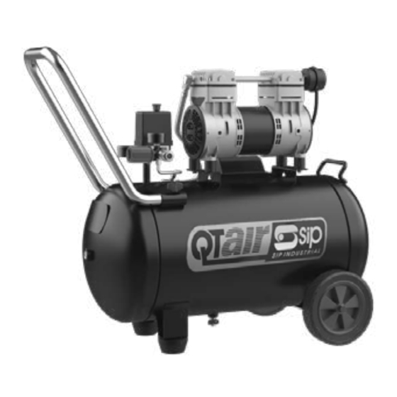
Summary of Contents for SIP QT Air 04381 QT 24/10
- Page 1 10 & 04382 QTA50/10 Read and understand this operator's manual thoroughly before using the product. It contains important information for your safety as well as operating and maintenance advice.
-
Page 2: Table Of Contents
Contents Safety Guidelines....................3 Key Parts Diagram....................5 Parts Description ....................6 Assembly ....................... 7 Operating Instructions..................... 8 Maintenance........................9 Troubleshooting..................... 10 Technical Specifications..................12 Exploded View ....................... 13 Parts List........................ 14 Read all instructions and follow them with use of this product. -
Page 3: Safety Guidelines
Safety Guidelines Important Safety Information The manufacturer cannot possibly anticipate every possible circumstance that might involve a hazard. The warnings work method, or operating technique that the manufacturer does not specifically recommend, you must satisfy yourself that it is safe for you and others. You must also make sure that the procedure, work method, or operating technique that you choose does not render the compressor unsafe. - Page 4 Safety Information WARNING compressor. High pressure air could result in death or serious injury. Never operate above maximum operating pressure of the spray gun or tool. Drain water from tank after each use. Do not weld or repair tank. Do not operate with pressure switch or safety valve set above maximum allowable working pressure. Hot compressor surfaces could result in serious injury.
-
Page 5: Key Partsdiagram
Key PartsDiagram Item Description Item Description Motor & Pump Assembly Quick Connector Air Outlet Air Receiver 24L or 50L Air Tank Ball Valve Pressure Relief Safety Valve Tank Pressure Gauge Air Pressure Regulator ON / OFF - Pressure Switch Regulated Pressure Gauge Mains Lead... -
Page 6: Parts Description
Key Parts Description The motor is used to power the pump. It contains a thermal overload protector. If ELECTRIC MOTOR: the motor overheats for any reason, the thermal overload protector will shut it down in order to prevent the motor from being damaged. The pump is used to compress the air and discharge it into the tank via the AIR COMPRESSOR PUMP: piston moving up and down in the cylinder. -
Page 7: Assembly
Assembly PREPARATION Before beginning assembly of product, make sure all parts are present. Compare parts with package contents list and hardware contents list. If any part is missing or damaged, do not attempt to assemble the product. Estimated Assembly Time: 5 minutes Tools Required for Assembly (not included): ASSEMBLY INSTRUCTIONS 1. -
Page 8: Operating Instructions
Operating Instructions BEFORE EACH START UP 1. Press the ON/OFF switch down to the off position. 2. Turn the air pressure regulator knob (D) counterclockwise until it stops. 3. Attach air hose/accessories or air tools (not included) to the airline outlet (F). Risk of bursting. -
Page 9: Maintenance
Maintenance WARNING: To avoid personal injury, always shut off and unplug the unit and relieve all air pressure from the system before performing. Regular maintenance will ensure trouble-free operation. SERVICE TASK DESCRIPTION INTERVAL To prevent corrosion inside the tank, the condensation must be drained at the end of every workday. -
Page 10: Troubleshooting
5. Hole in air hose. 6. WARNING: Immediately replace tank. DO NOT attempt to repair. 6. Tank leaks. 7. Contact SIP (Industrial Products) Ltd. 7. Blown seals. 8. Contact SIP (Industrial Products) Ltd. 8. Valve leaks. 9. Contact SIP (Industrial Products) Ltd 9. - Page 11 Troubleshooting PROBLEM POSSIBLE CAUSE CORRECTIVE ACTION 1. Tank pressure exceeds preset pressure 1. Motor will start automatically when tank switch limit. pressure drops below tank cut-in pressure. 2. Fuse blown or circuit breaker tripped. 2. Replace blown fuse or reset circuit breaker.
-
Page 12: Technical Specifications
Technical Specification Model 04381 QT 24/10 230v 50Hz Supply 1.3HP / 1KW Motor Power 4 / 1400rpm Motor Poles / Speed Oil - Less Pump 7.3ft /Min - 208Litres/Min Piston Displacement 5.4ft /Min -153Litres/Min Free Air Delivered 10Bar - 145psi Maximum Pressure 24Litres Receiver Size... -
Page 13: Exploded View
Exploded View 04381... -
Page 14: Parts List
Parts List 04381 Item Description Item Description Air Filter Drain Valve Delivery Pipe Screw M5 x 20 Motor Pump Unit 24Litre Air Receiver Elbow Connector Non Return Valve Bleed Pipe Nut M10 Pressure Safety Valve Spring Washer 10mm Pressure Switch Wheel Mains Lead Wheel Axle... - Page 15 Exploded View 04382...
- Page 16 Parts List 04382 Item Description Item Description Receiver Bung Air Filter Tube Rubber Mounts Wing Nut Capacitor Cover Non Return Valve Capacitor Cover Screws Handle Capacitor Retaining Ring Bleed Pipe Capacitor Mains Lead Crimp Connector Air Pressure Regulator Self Tapping Screw 3.9 x 14 Quick Coupler Cable Clamp Working Pressure Gauge...
- Page 17 England As The Manufacturer's Authorised Representative Declare that the SIP QT 24/10 Air Compressor - SIP Part No. 04381 SIP QT 50/10 Air Compressor - SIP Part No. 04382 Conforms to the requirements of the following Directive/s, as indicated. 2014/30/EU...
- Page 18 This will allow the recycling of raw materials and help protect the environment. FOR HELP OR ADVICE ON THIS PRODUCT PLEASE CONTACT YOUR DISTRIBUTOR, OR SIP DIRECTLY ON: TEL: 01509500400 EMAIL: sales@sip-group.com or technical@sip-group.com www.sip-group.com Ref: 08OCT2020...
Need help?
Do you have a question about the QT Air 04381 QT 24/10 and is the answer not in the manual?
Questions and answers