
Related Manuals for Kicker KEY200.4


Summary of Contents for Kicker KEY200.4
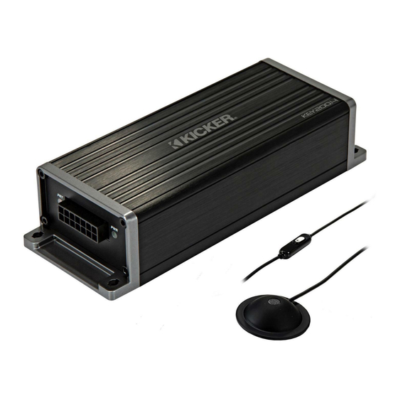
- Page 1 Owner’s Manual Manual del Propietario Manuel d’utilisation Benutzerhandbuch KEY200.4 4-Channel DSP Amplifier...
-
Page 2: Table Of Contents
Contents Overview ......3 Specifications ......4 Installation ...... 5 Mounting ....... 5 Wiring ........6 Operation ..... 10 Features ......10 KEY Auto Setup ....14 Auto Setup FAQ ....17 Error Codes ......19 Troubleshooting .... 20 Warranty ...... 21 English... -
Page 3: Overview
VENTILATION. SUBWOOFERS SHOULD BE MOUNTED WITH AT LEAST 1 INCH (2.5CM) CLEARANCE BETWEEN THE FRONT OF THE SPEAKER AND ANY SURFACE. KICKER PRODUCTS ARE CAPABLE OF PRODUCING SOUND LEVELS THAT CAN PERMANENTLY DAMAGE YOUR HEARING! TURNING UP A SYSTEM TO A LEVEL THAT HAS AUDIBLE DISTORTION IS MORE DAMAGING TO YOUR EARS THAN LISTENING TO AN UNDISTORTED SYSTEM AT THE SAME VOLUME LEVEL. -
Page 4: Specifications
Specifications Model: KEY200.4 RMS Power, AMP1 and AMP2 @ 14.4V, 4Ω stereo, ≤ 1% THD+N 50W x 4 Length [in, cm] 7-3/8, 18.7 Height [in, cm] 1-11/16, 4.3 Width [in, cm] 2-3/4, 7 AMPS 1-2: 20Hz–20kHz Frequency Response [Hz] Signal-to-Noise Ratio [dB] >90dB, A-weighted, re:... -
Page 5: Installation
Installation Mounting Choose a structurally sound location to mount your KICKER amplifier. Make sure there are no items behind the area where the screws will be driven. Choose a location that allows at least 4” (10cm) of open ventilation for the amplifier. If possible, mount the amplifier in the climate-controlled passenger compartment. -
Page 6: Wiring
Wiring Disconnect the vehicle’s battery to avoid an electrical short. Then connect the ground wire to the amplifier. Make the ground wire short, 24” (60cm) or less, and connect it to a paint-and-corrosion-free, solid, metal area of the vehicle’s chassis. Adding an additional ground wire of this same gauge (or larger) between the battery’s negative post and the vehicle chassis is recommended. - Page 7 The KEY amplifier is capable of using the wiring directly from your head unit, but for best results it is recommended you use power and ground wiring from the vehicle’s battery and chassis. KICKER recommends 14 gauge wire. If needed, cut off the RCA connections to use hi-level input.
- Page 8 For multiple amplifier installations where distribution blocks are used, each amplifier should have its proper-rated fuse, or breaker, installed between the amplifier and the distribution block within eighteen inches of the block, or on the distribution block if it provides for fusing. The primary power wire should also be fused between the battery and distribution block, within eighteen inches of the battery’s positive terminal, with a fuse or breaker rated at least to the...
- Page 9 STANDARD (FULL-RANGE) WIRING minimum impedance of 4 ohms per channel – – – – BI-AMP WIRING minimum impedance of 4 ohms per channel woofers must be installed to rear (AMP 2) channels tweeters must be installed to front (AMP 1) channels Bi-Amp switch must be ON! –...
-
Page 10: Operation
The DC offset mode detects a 3V DC offset on the speaker wires when the source unit has been turned on. RADIO DETECT: The RCA inputs on KICKER KEY amplifiers are capable of receiving either Hi or Low- level signals from your source unit. If you are using... - Page 11 For a quick setup, turn the source unit up to about 3/4 volume (if the source unit goes to 30, turn it to 25). KICKER recommends using the test tones at www.KICKER.com/support/ to reach the most accurate and best performing settings.
- Page 12 BI-AMP MODE: The majority of systems require this switch to be OFF. Turn ON only if your speakers are wired in “Bi-Amp” mode (refer to BI-AMP operation picture on page 9). The Bi-Amp mode is to be specifically used without passive crossovers. Possible usages are with component speakers (two woofers and two tweeters), or with door woofers and dash speakers.
- Page 13 LIMITER: The LIMITER may engage for multiple reasons, as indicated by the LIMITER LEDs. This is to protect your speakers and allow for continuous playback. The LIMITER will engage during: • Engine start: The KEY is a Start-Stop compatible amplifier; it will not turn off during engine start. When your vehicle’s engine is starting there is a voltage dip in the +12V line.
-
Page 14: Key Auto Setup
Setup process has been completed, or clear previous Auto Setup settings. The Auto Setup consists of several tune-up steps including individual speaker equalization, KICKER EQ, time delay and speaker sensitivity matching. If a setting is defeated with the DIP switches on the KEY panel, the settings will be registered in memory and can be applied or cleared. - Page 15 2. Close the car windows, turn off the engine, turn off the HVAC. Install the microphone to the top of the driver’s side headrest. Make sure the microphone faces up, pointing as straight as possible to the roof. run mic wire mic facing up headrest 3.
- Page 16 5. Begin the Auto Setup by quick-pressing the KEY Activation Button. Once initialized, you will hear repeating tones (beeps), which indicate that you must exit the vehicle and close the door. You will have 10 seconds until the process begins. Beeps and noises during the KEY Auto Setup process can be loud.
-
Page 17: Auto Setup Faq
Auto Setup FAQ Q: How silent must the ambient noise be in order for the Auto Setup work properly? A: As silent as possible, both inside and outside the vehicle. The HVAC should be off and the windows rolled up, with as few obstructions in the vehicle as possible. - Page 18 A: Ensure all speakers connected to the KEY amplifier are wired in phase with each other. Be sure to check both the amplifier side and the speaker side of the wiring. Visit www.kicker.com/tech to download the pink noise profile best suited for your listening habits! English...
-
Page 19: Error Codes
Error Codes Beeps Reason Troubleshooting Action Tweeter found, but the BI- Enable the BI-AMP switch AMP switch is off BI-AMP switch is on, but Make sure all wiring is properly there is no sound from a connected to the correct amplifier channel channels. -
Page 20: Troubleshooting
There are Power (PWR) & Protection (PRT) LEDs on the side panel of your KICKER KEY series amplifier. Depending on the state of the amplifier and the vehicle’s charging system, the LEDs will glow either green or red. When the green LED is lit, this indicates the amplifier is turned on and no trouble exists. -
Page 21: Warranty
Should service be necessary under this warranty for any reason due to manufacturing defect or malfunction during the warranty period, KICKER will repair or replace (at its discretion) the defective merchandise with equivalent merchandise. Warranty replacements may have cosmetic scratches and blemishes. - Page 22 Service performed by anyone other than KICKER HOW LONG WILL IT TAKE? KICKER strives to maintain a goal of one week turnaround for all electronics (amplifiers, crossovers, equalizers, etc.) returns. Delays may be incurred if lack of replacement inventory or parts is encountered.
- Page 23 Estimado amante de la música: ¡Gracias y felicitaciones por su compra del amplificador de audio inteligente KEY200.4 de Kicker! El amplificador de la serie KEY combina nuestros diseños de audio de calidad reconocida con tecnología digital moderna, para brindar el mejor rendimiento de audio en un vehículo. El amplificador KEY emplea circuitos digitales para sincronizar la ganancia, controlar el divisor de frecuencia, ecualizar automáticamente, comprimir, limitar, retardar el tiempo y mucho más.
- Page 24 Désactivez l'annulation active du bruit et l'amélioration du bruit avant de commencer. Vous devrez charger une source de bruit rose à partir de votre unité principale, qu'il s'agisse d'un CD, de MP3, de la voie AUX, de Bluetooth, d'USB, etc. Un signal audio non compressé est recommandé pour donner les meilleurs résultats, car cela garantira une pleine amplitude sur tout le spectre des fréquences (20 Hz - 20 kHz). Consultez www.kicker.com/tech pour télécharger les profils de bruit rose les plus adaptés à votre écoute habituelle ! 1.
Need help?
Do you have a question about the KEY200.4 and is the answer not in the manual?
Questions and answers