Table of Contents
Advertisement
Quick Links
Models:
EKW117
EKW190
EKW235
EKW295
Warning:
Read and fully understand this manual before attempting to install this Water heater. It can
cause personal injury and damage to the Water heater when you do not read the manual
and/or do not obey the instructions.
EcoKnight
Circulating type gas condensing water
heater
Installation, Commissioning and
Maintenance Instructions
Advertisement
Table of Contents

Related Manuals for Lochinvar EcoKnight EKW117


Summary of Contents for Lochinvar EcoKnight EKW117
- Page 1 EcoKnight Circulating type gas condensing water heater Installation, Commissioning and Maintenance Instructions Models: EKW117 EKW190 EKW235 EKW295 Warning: Read and fully understand this manual before attempting to install this Water heater. It can cause personal injury and damage to the Water heater when you do not read the manual and/or do not obey the instructions.
- Page 2 OCUMENT IDENTIFICATION Article Language Version Amended by EcoKnight water heater ICM English Launch Page 1 of 75...
- Page 3 Warranty) for the warranty provisions. IABILITY User Lochinvar accepts no liability when the water heater is not used correctly and requires the user to: • Read this manual carefully and obey the instructions. • Ask your installation engineer for advice about the use of the Water heater.
- Page 4 OMPLIANCE To safely produce low temperature hot water, the design and construction of the EcoKnight water heaters is in accordance with: • UK and European Regulations 2016/426 on appliances burning gaseous fuels (GAR). • UK and European Standard for Gas–fired central eating boilers (BS EN15502). •...
- Page 5 ABOUT THIS MANUAL COPE This manual gives information about safe and correct use of the Water heater and how installation, maintenance and service activities must be carried out correctly. You must obey the instructions in this manual. Warning Read and fully understand this manual before attempting to install this Water heater.
- Page 6 This manual contains the following text styles/symbols for situations that may endanger users/engineers, cause damage to equipment or need special attention: Note A note gives more information on a topic. Caution Obey the caution instructions to prevent damage to the Water heater. Warning Obey the warning instructions to prevent danger of personal injury, and serious damage to the Water heater.
-
Page 7: Table Of Contents
TABLE OF CONTENTS USER PART ..........................7 Safety ............................7 Control interface........................8 Use ............................9 INSTALLATION PART ......................... 11 Introduction .......................... 11 Safety devices ........................12 Principle parts ........................13 Packaging ..........................17 Conditions ..........................17 Water composition ....................... 18 Working clearances ...................... -
Page 8: User Part
USER PART AFETY Lochinvar cannot be held responsible for damages or injuries which can lead back to: Failure to follow the instructions provided in this manual. Carelessness during use or maintenance of the Water heater. Every user must study the user part of this manual and must follow the instructions in this part of the manual strictly. -
Page 9: Control Interface
Temperature, Outlet Water Temperature, Flue Temperature, and HW Tank Temperature. •E-The Navigation Section is located down the left side of the screen. There are five (5) sections located below the Lochinvar icon: Home, View, Setup, Information (About), and Settings. The Home Section is the screen shown in Figure 1. -
Page 10: Use
setting section enables several interface setup features including Time Setup, Temperature Unit Select and System Update. Warning There are no user serviceable parts inside the EcoKnight water heater, only suitably qualified engineers can remove any of the panels. If the water heater is not operating correctly contact your service agent. - Page 11 To set a parameter During normal operation, set point temperatures can be adjusted from the Home Screen by pressing the DETAIL button in the demand section under Setpoint as shown below. 1. To change a set point, use the set point slider feature or the PLUS (+) and MINUS (-) buttons as shown below in Figure 3.
-
Page 12: Installation Part
INSTALLATION PART NTRODUCTION is a fully modulating condensing gas water heater; it can be used to supply hot NIGHT water for domestic hot water via a direct vessel. EcoKnight features the SMARTOUCH interface which allows for simple parameter changes and shows the status of the appliance without having to scroll through multiple screens. -
Page 13: Safety Devices
AFETY DEVICES EcoKnight water heaters have the following safety devices fitted: 1. Temperature sensors, inlet, outlet, flue gas and a high limit sensor are fitted to ensure accurate temperature control and to ensure a hazardous situation does not occur. 2. Air/gas pre-mix control, this achieves optimum efficiency and prevents gas flowing should there be a fault with the inlet fan. -
Page 14: Principle Parts
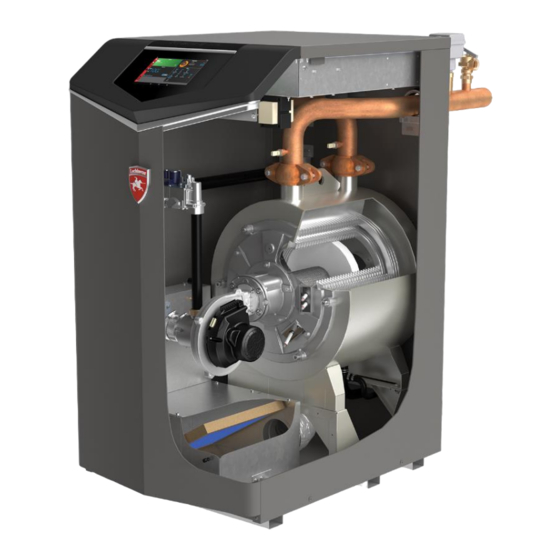
RINCIPLE PARTS The EcoKnight water heater is a condensing, fully modulating gas water heater designed to supply domestic hot water via a direct vessel. EcoKnight water heaters feature: See exploded view 1. Stainless steel heat exchanger- Allows system water to flow through specially designed coils for maximum heat transfer, while providing protection against flue gas corrosion. - Page 15 If flow is discontinued during operation for any reason, the flow switch will break the control circuit and the unit will shut down. Lochinvar can supply a suitable flow switch on request, or the installer can use their own.
- Page 16 Figure 4 EcoKnight model EKW117 exploded view. Rear view Front view Left hand side view Right hand side view Page 15 of 75...
- Page 17 Figure 5 EcoKnight model EKW190-EKW295 exploded view. Front view Rear view Left hand view Right hand view Page 16 of 75...
-
Page 18: Packaging
Carefully inspect the water heater for any damage and report immediately to Lochinvar customer service if any is found. The water heater is supplied on a pallet, to remove first remove the four bolts securing the water heater to the pallet as in detail B. -
Page 19: Water Composition
ATER COMPOSITION The Lochinvar EcoKnight contains a stainless-steel heat exchanger; therefore, care must be exercised to ensure that the system water and any water treatment are compatible. Whenever a new water heater is connected to an existing system, the pipework must be thoroughly cleaned and flushed to remove debris, rust particles, carbonate deposits and any existing water treatment that might be incompatible with the heat exchanger. -
Page 20: Working Clearances
ORKING CLEARANCES To maintain sufficient clearances for cooling and access for maintenance the EcoKnight should have the following clearances: Installation in a compartment Figure 6 compartment clearances Installation within a plantroom Figure 7 plantroom clearances See ventilation requirements Page 19 of 75... -
Page 21: Installation Schematic S
NSTALLATION SCHEMATIC S Figure 8 Single water heater Table 1 key to drawings Figure 8 and 9 Key to drawings Item Description Isolation valve Pressure reducing valve Non return valve Lockshield valve Expansion vessel Tundish Expansion valve (pressure relief) T&P valve Circulating Pump Drain valve Flow switch... - Page 22 Figure 9 Multiple water heaters Page 21 of 75...
-
Page 23: Water Connections
A suitable shunt pump can be supplied as an ancillary by Lochinvar, or we can assist in ensuring your own pump is suitable. - Page 24 Figure 10 water heater connections Table 2 water heater pipework connection sizes Water heater Water connections A and B Gas connection C EKW117 2" 1" EKW190 2" 1¼" EKW235 2" 1¼" EKW295 1¼" 2½" Table 3 water heater flow rates and pressure drop. Model Minimum pipe size l/sec...
-
Page 25: Water Heater Shunt Pump
2. 6 Metres of pipework, 4no 90 elbows and 2no fully ported valves. If the installation is outside these parameters the water heater shunt pump and pipework size will need to recalculated, Lochinvar can offer larger pumps for more complex systems. Contact Lochinvar technical support for assistance. - Page 26 EKW190 EKW235 Page 25 of 75...
- Page 27 EKW295 Table 5 shows the pipework header sizing required to ensure the correct flow rate is maintained between the EcoKnight water heater(s) and storage vessel(s) Using the example schematics shown figures 11 and 12 and assuming the EcoKnight water heater is an EKW190 in both cases the header would be sized as: Single unit = as there is only a single heater there is no common header so all the pipework should be 54mm.
- Page 28 If your installation is outside the scope of this guidance, please contact Lochinvar Technical support before proceeding with the installation.
- Page 29 Condensate drainpipe The condensate drain is placed at the centre and at the bottom of the water heater and has a ½” 12.7mm hose discharge. Connect this hose to the condensate trap and then pipe to drain. Connect the electrical plug alongside the hose to the condensate trap. Condensate with be slightly acidic with a Ph between 3 and 5.
-
Page 30: Gas Connection
Failure to follow these instructions may result in fire. The Lochinvar EcoKnight range is suitable for use on second family gasses 2H - G20 - 20mbar only. EcoKnight has also been tested for use on G20Y20 (20% Hydrogen) and has been found to operate satisfactory should this gas become available in the future in the UK. -
Page 31: Lpg Gas
When connecting /fitting any pipework to the water heater supplied gas pipe a second wrench must to be used to prevent the gas pipe within the water heater turning as per drawing below. Caution Before carrying out any gas pressure testing on the system pipework close the manual isolation valve on the water heater if the test pressure is to be above 30mbar. -
Page 32: Flue System
T120. Note Before installation of any flue system read the installation manual carefully for both the appliance and flue system to be used. Information on the flue system supplied by Lochinvar can be found within this manual. Warning Aluminium flue pipe must not be used on this appliance as it may lead to premature failure of the heat exchanger and will invalidate the warranty. - Page 33 Flue discharge The flue system must ensure safe and efficient operation of the equipment to which it is attached, protect the combustion process from wind effects and disperse the products of combustion to open external air. The flue must terminate in a freely exposed position and be so situated as to prevent the products of combustion entering any opening in a building.
- Page 34 Flue terminal positions Table 7 Flue terminal positions (use in conjunction with picture above) EKW117 EKW190 EKW235 EKW295 Location Description Directly below an opening, air brick, opening windows etc. 2500 2500 2500 Above an opening, air brick, opening windows etc. 1468 1793 Horizontally to an opening, air brick, opening windows etc.
- Page 35 Further to the requirements in IGEM/UP/10 Edition 4 +A: 2016 Section 8 under clause 8.7.3.3 and Figure 7 the following risk assessment gives guidance for the positioning of horizontal flues. This form should be completed before work commences and undertaken by a person who is competent to undertake the risk assessment.
- Page 36 Approved flue systems The EcoKnight water heater is approved for use on the following types of flue system, the most popular are described in more detail on the following pages: Type according EN 15502-2-1: 2012 Performance Description * Roof terminal * Without draught diverter * Water heater room air supply.
- Page 37 B23 Flue systems Flue system specifications •MANUFACTURER MUELINK AND GROL (M&G) •TEMPERATURE CLASS T120 •FLUE GAS MATERIAL PP Model Number EKW117 EKW190 EKW235 EKW295 FLUE DATA TYPE B Nominal flue diameter Minimum flue gas temp °C Average flue gas temp °C Maximum flue gas temp.
- Page 38 B23 Flue items available Item no EKWCF010 Starter kit EKW117 Item Item No Equivalent length mtr EXPANDER Ø100mm - Ø130mm PP M85126 EXPANDER Ø130mm - Ø150mm M70262 SAMPLING POINT Ø150mm PP M70326 BEND 90° Ø150mm PP LV310665 APPLIANCE AIR INLET GUARD Ø100mm M86787 Total equivalent length mtr Item no EKWCF011...
- Page 39 C13 Flue systems Flue system specifications •MANUFACTURER MUELINK AND GROL (M&G) •TEMPERATURE CLASS T120 •FLUE GAS MATERIAL PP Model Number EKW117 EKW190 EKW235 EKW295 FLUE DATA TYPE C & C Nominal flue diameter Nominal air inlet diameter Minimum flue gas temp °C Average flue gas temp °C...
- Page 40 C13 Flue items available Item no EKWHF010 Starter kit EKW117 Equivalent Item Item No length meter EXPANDER Ø100mm - Ø130mm PP M85126 EXPANDER Ø130mm - Ø150mm M70262 SAMPLING POINT Ø150mm PP M70326 BEND 90° Ø150mm PP LV310665 14.2 HORIZONTAL TERMINAL Ø150/220mm ALU M76561 Total equivalent length meter 20.7...
- Page 41 C33 Flue systems Flue system specifications •MANUFACTURER MUELINK AND GROL (M&G) •TEMPERATURE CLASS T120 •FLUE GAS MATERIAL PP Model Number EKW117 EKW190 EKW235 EKW295 FLUE DATA TYPE C & C Nominal flue diameter Nominal air inlet diameter Minimum flue gas temp °C Average flue gas temp °C...
- Page 42 C33 Flue items available Item no EKWVF010 Starter kit EKW117 Equivalent Item Item No length meter EXPANDER Ø100mm - Ø130mm PP M85126 EXPANDER Ø130mm - Ø150mm M70262 SAMPLING POINT Ø150mm PP M70326 BEND 90° Ø150mm PP LV310665 14.2 CONCENTRIC VERTICAL TERMINAL Ø150/220mm ALU M86929 Total equivalent length meter 20.7...
- Page 43 C53 Flue systems Flue system specifications •MANUFACTURER MUELINK AND GROL (M&G) •TEMPERATURE CLASS T120 •FLUE GAS MATERIAL PP Model Number EKW117 EKW190 EKW235 EKW295 FLUE DATA TYPE C & C Nominal flue diameter Nominal air inlet diameter Minimum flue gas temp °C Average flue gas temp °C...
- Page 44 C53 Flue items available Item no EKWTF010 Starter kit EKW117 Equivalent Item Item No length meter EXPANDER Ø100mm - Ø130mm PP M85126 EXPANDER Ø130mm - Ø150mm M70262 SAMPLING POINT Ø150mm PP M70326 BEND 90° Ø150mm PP LV310665 14.2 AIR INLET TERMINAL Ø150mm LG800015A ROOF TERMINAL 150MM M70359...
- Page 45 C63 Flue systems In general, Water heaters are certified with their own purpose supplied Concentric or Twin Pipe flue systems, C63 certified appliances allow the installer to use other flue systems when installing the Water heaters however, they must be of a suitable minimum standard as per Table below.
-
Page 46: Combustion Ventilation
OMBUSTION ENTILATION The following information is based on single water heater installations only. If more than one water heater is being used, BS6644 or IGEM UP10 (as appropriate) should be consulted to calculate the necessary requirements. Type B installations When used as a Type B (open flue) appliance, the combustion air requirements are as follows: Table 9 Ventilation requirements Type B flue systems. -
Page 47: Electrical Connections
LECTRICAL CONNECTIONS Wiring external to the equipment must be installed in accordance with the I.E.E. Regulations and any local regulations that apply. Warning Leave the water heater electrically isolated until you are ready to commission it. This appliance must be earthed. A suitably competent person must check wiring. - Page 48 Figure 15 Figure 16 high voltage connections Caution The three pump outputs are relays, each can accept up to 7amp maximum. If the pumps are larger than this, please contact Lochinvar Technical support for further assistance. Page 47 of 75...
- Page 49 Low voltage connections Route all low voltage connections through the knockouts in the rear of the water heater as shown in Figure 15. All connections should be secured using an appropriate cord anchorage. Figure 17 low voltage connections, (see descriptions on next page for details) Page 48 of 75...
- Page 50 Connection descriptions Note The low voltage board fitted to EcoKnight water heaters is also used on Herald heating boilers, as such some of the connections are not used. These are shown on the descriptions below ALARM CONTACTS Volt free – Close on alarm. An internal volt free contact across pins 1 and 2 will close in the event of the heater locking out.
- Page 51 29-30 TANK SENSOR 24VAC Output – To ensure close control of the DHW temperature and prevent cycling a sensor should be located in the bottom third of the direct storage vessel and connected to terminals 29 and 30 to control the output from the water heater. This connection is not polarity sensitive.
- Page 52 Figure 18 Fuse Location The EcoKnight has three internal fuses. All are slow blow fuses, located and rated as follows: • F1-5A • F2-3.15A • F3-80A The water heater has three spare fuses in a plastic bag attached to the control module cover. Only replace with an equivalent rated fuse.
-
Page 53: Commissioning
OMMISSIONING Prior to start-up Caution: A person deemed competent must be responsible for the commissioning of this equipment. Before attempting to commission any equipment, ensure that personnel involved are aware of what action is about to be taken and begin by making the following checks: Water side The system should be thoroughly flushed out with cold water without any circulating pumps... - Page 54 General checks prior to lighting 1. Flueway passages are clear. 2. Adequate ventilation exists in the plant room (if necessary). 3. The system is fully charged with water, ready to receive heat. All necessary valves are open, and all allied pumps are circulating water. 4.
- Page 55 Figure 19 SMART TOUCH home screen Use the following procedure to set the clock: 1. Press the SETTINGS button on the left-hand side See Figure 2. Press the SET button across from the date and time 3. Proceed to set the date, time, and time zone. NOTE: Automatic Time Zone will not work unless the unit is connected to a Wi-Fi network.
- Page 56 The CO levels shall be less than 150 ppm for a properly installed unit. Note If the combustion is not within the specified range, reference the Troubleshooting Section of this Manual for possible causes and corrective actions or contact Lochinvar Technical Support. Table 11 CO levels Natural Gas 8.4% - 9.4%...
- Page 57 Adjust set point temperature(s) During normal operation, set point temperatures can be adjusted from the Home Screen by pressing the DETAILS button under setpoint See Figure 1. To change a set point, use the set point slider feature or the PLUS (+) and MINUS (-) buttons to adjust the set points as shown in Figure 2.
- Page 58 Tank Set Point Differential When a tank sensor is installed, the tank temperature must drop this amount below the tank set point (DHW Tank Set point parameter) before the water heater turns back on. The installer can adjust this setting by accessing the Tank Set point Differential parameter. The minimum setting is 0°C, and the maximum is 22°C.
- Page 59 last water heater (the third in our example) will turn off and the Cascade will increase the rates of the remaining water heaters to provide the equivalent total output as before (3 x 30%) / 2 =45% in our example). Efficiency optimization is automatically selected when water heaters of different sizes are programmed into the Leader control (see Water heater Size on this page).
- Page 60 How the water heater operates The EcoKnight water heater uses an advanced stainless steel heat exchanger and electronic control module that allows fully condensing operation. The fan pulls in air and pushes flue products out of the water heater through the heat exchanger and flue piping. The control module regulates fan speed to control the water heater firing rate.
- Page 61 Protection features Outlet temperature, flue temperature, and temperature rise limiting. The outlet temperature is monitored by the water heater outlet temperature sensor. When the outlet temperature exceeds 85°C, the unit will reduce the fan speed. If the outlet water temperature exceeds 90°C the control will shut the unit down until it cools off.
- Page 62 Monitoring external limits Connections are provided on the connection board for external limits such as flow switch, low water cut-off, gas pressure switches, and a louver proving switch. The SMART TOUCH will shut off the burner and inhibit relighting whenever any of these external limits open. Run-time and alarm outputs The water heater provides dry contacts for indicating when the water heater is running, and when it is unable to operate.
- Page 63 Cascade When multiple water heaters are installed, they can be wired together in a cascade sequence. A maximum of eight water heaters can be controlled from a single control. In this application one water heater would be designated as the Leader control and all others would be designated as Member controls.
- Page 64 Table 12 sequence of operation OPERATION Upon a call for heat, the control turns on the Primary DHW pump. The control confirms that the low water cut-off / flow switch contacts are closed and energizes the louvers (optional) The control confirms that the gas pressure switch, blocked drain switch, limits, louver proving switch (optional), and contacts close.
-
Page 65: Maintenance Schedules
SERVICE AND MAINTENANCE PART AINTENANCE SCHEDULES Service technician Service technician (See the following pages for instructions) General: • Address reported problems • Inspect interior; clean and vacuum if necessary; Including air inlet filter • Clean condensate trap and fill with fresh water •... - Page 66 Building owner Owner maintenance Check water heater area Check pressure/temperature gauge Check vent piping Check air piping Check air and vent termination screens Check relief valve Check condensate drain system Check air vents Check strainer Test low water cut-off (if used) Reset button (low water cut-off) Check water heater piping (gas and water) for leaks Operate relief valve...
-
Page 67: Maintenance Procedures
AINTENANCE PROCEDURES Refer to separate EcoKnight Service manual. Scan the QR code to access the EcoKnight service manual ROUBLESHOOTING Refer to separate EcoKnight Service manual. Scan the QR code to access the EcoKnight service manual Page 66 of 75... -
Page 68: Appendix
APPENDIX PPENDIX ECHNICAL DATA TABLE EKW 117 EKW 190 EKW 235 EKW 295 Model Number GENERAL DATA 0063DO3450 Product I.D. Number Classification 128.1 187.3 226.6 285.9 Input (gross) 115.3 168.7 204.1 257.5 Input (net) 11.5-113.1 16.7-184.4 23.1-226.8 28.9-283.1 Output (PmMin-PnMax) 10:1 10:1 10:1... -
Page 69: Appendix 2 Dimensions
PPENDIX IMENSIONS Model Number EKW117 EKW190 EKW235 EKW295 1143 1143 1143 1143 A Height 1080 1080 1270 B Length C Width Flow/return pipework Gas pipework Flue outlet Air inlet Page 68 of 75... -
Page 70: Appendix 3 Erp Data Table
PPENDIX ATA TABLE Type Circulating water heater: EKW117 EKW190 EKW235 EKW295 Condensing boiler: Low temperature boiler: B11 boiler: Cogeneration space heater: Combination heater: Unit: Rated heat output P-rated (P4) at 60-80°C 111.7 163.1 197.3 248.4 Heat output (p1) 30% at 30-37°C 37.8 55.3 66.6... -
Page 71: Appendix 4 Wiring Diagram
PPENDIX IRING DIAGRAM Page 70 of 75... -
Page 72: Appendix 5 Ladder Diagram
PPENDIX ADDER DIAGRAM Page 71 of 75... -
Page 73: Appendix 6 Declaration Of Conformity
PPENDIX ECLARATION OF ONFORMITY Page 72 of 75... -
Page 74: Appendix 7 Warranty
The low water content stainless steel heat exchanger has a manufacturing defect warranty of up to 5(five) years. This provides coverage to the end user via Lochinvar that if the heat exchanger becomes unserviceable due to a material or workmanship defect it will be replaced. - Page 75 (6) Scope of the warranty The obligations of Lochinvar Ltd. pursuant to the specified warranty are limited to free delivery from the warehouse of the replacement assemblies, parts, or water heater, respectively. Labour, installation, and any other costs associated with the replacement will not be accepted by Lochinvar Ltd.
- Page 76 Page 75 of 75...
Need help?
Do you have a question about the EcoKnight EKW117 and is the answer not in the manual?
Questions and answers