Table of Contents

Related Manuals for Lochinvar EcoKnight EKW85CE


Summary of Contents for Lochinvar EcoKnight EKW85CE
- Page 1 The EcoKnight™ range High Efficiency Gas Fired Condensing Water Heaters Installation, Commissioning and Maintenance Instructions Models: EKW45CE EKW60CE EKW85CE EKW115CE EKW145CE EKW175CE EKW205CE EKW235CE INS0011 Issue No 9 | October 2013...
-
Page 2: Table Of Contents
Table of Contents INTRODUCTION ........................................4 PRINCIPAL PARTS ....................................... 5 TECHNICAL DATA ........................................ 9 GENERAL REQUIREMENTS ..................................... 11 RELATED DOCUMENTS ..................................... 11 WATER QUALITY ....................................... 12 LOCATION ........................................... 12 PLANT ROOM REQUIREMENTS ................................12 GENERAL REQUIREMENTS ..................................12 CLEARANCES ......................................13 CONDENSATE DRAIN .................................... - Page 3 13.5 TEMPERATURE ADJUSTMENT PROCEDURE ............................39 13.6 INSTALLATION NOISE ....................................40 14.0 LPG FUEL ..........................................40 14.1 RELATED DOCUMENTS ..................................... 40 14.2 CONVERSION TO LPG ....................................40 14.2.1 EKW45CE – EKW85CE .................................. 41 14.2.2 EKW115CE ...................................... 42 14.2.3 EKW145CE (BEFORE SERIAL NUMBER L09H10120786) ......................43 14.2.4 EKW145CE (FROM SERIAL NUMBER L09H10120786) .......................
-
Page 4: Introduction
INTRODUCTION The Lochinvar EcoKnight™ range is a floor standing direct gas fired condensing water heater. The equipment comprises of stainless steel radial burner assembly and heat exchanger that permits fully condensing operation. EcoKnight™ water heaters should be used in conjunction with an appropriately sized storage vessel (available from Lochinvar Limited as an ancillary option) ... -
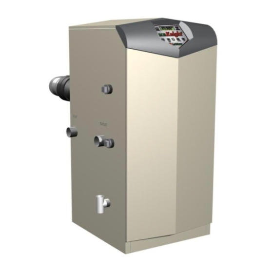
Page 5: Principal Parts
PRINCIPAL PARTS ITEM DESCRIPTION FUNCTION Allows water to flow through specially designed coils for maximum heat transfer, while providing Stainless steel heat exchanger protection against flue gas corrosion. The coils are encased in a jacket that contains the combustion process. Heat exchanger access cover Allows access to the combustion side of the heat exchanger coils. - Page 6 FRONT VIEW REAR VIEW MODELS EKW45CE – EKW60CE MODELS EKW45CE – EKW60CE LEFT SIDE (INSIDE UNIT) RIGHT SIDE (INSIDE UNIT) MODELS EKW45CE – EKW60CE MODELS EKW45CE – EKW60CE...
- Page 7 LEFT SIDE (INSIDE UNIT) REAR VIEW MODEL EKW85CE – EKW115CE MODEL EKW85CE – EKW115CE REAR VIEW LEFT SIDE (INSIDE UNIT) MODEL EKW145CE MODEL EKW145CE...
- Page 8 REAR VIEW LEFT SIDE (INSIDE UNIT) MODEL EKW175CE – EKW235CE MODEL EKW175CE – EKW235CE...
-
Page 9: Technical Data
TECHNICAL DATA Model Number EKW45CE EKW60CE EKW85CE EKW115CE EKW145CE EKW175CE EKW205CE EKW235CE GENERAL DATA Input (gross) – kW 44.0 61.5 83.5 116.9 146.5 175.8 205.2 234.5 Input (net) – kW 39.6 55.4 75.2 105.3 132.0 158.4 184.9 211.3 Recovery Rate (44° ΔT) – l/hr 1153 1567 2164... - Page 10 FIGURE 3.1 ENCLOSURE INSTALLATION CLEARANCES (mm) FIGURE 3.2 PLANT-ROOM INSTALLATION CLEARANCES (mm)
-
Page 11: General Requirements
GENERAL REQUIREMENTS The Lochinvar EcoKnight™ condensing water heater has been designed to operate trouble free for many years. These instructions should be followed closely to obtain the maximum usage and efficiency of the equipment. PLEASE read the instructions fully before installing or using the appliance. -
Page 12: Water Quality
350ppm. If these values are exceeded, contact Lochinvar Limited for further guidance. LOCATION 6.1 PLANT ROOM REQUIREMENTS The Lochinvar EcoKnight™ may only be installed in a room that complies with the appropriate ventilation requirements. The Lochinvar EcoKnight™ can be used as a type C or C appliance. -
Page 13: Clearances
Lochinvar Limited. This unit is capable of neutralising 4000 litres of condensate to a pH of 7.0 before releasing it to a drain. -
Page 14: Equipment Gas System Leak Check
7.6 EQUIPMENT GAS SYSTEM LEAK CHECK An approved gas inlet appliance isolating valve and union should be installed for each unit in a convenient and safe position and be clearly marked. Ensure that the gas inlet appliance isolating valve is in the OFF position. Although the equipment receives a gas leak check and gas train component integrity check prior to leaving the factory, transit and installation may cause disturbance to unions, fittings and components. -
Page 15: Flue System General Requirements
When used as a type C appliance, the approved, purpose designed adaptive flue system should be used. For further details, please contact Lochinvar Limited. When used as a Type B appliance, a suitable flue system constructed of Stainless Steel or Polypropylene with a temperature rating in excess of 120C should be used. -
Page 16: Water Heater Connection Assembly
8.7 WATER HEATER CONNECTION ASSEMBLY 8.7.1 EKW45CE – EKW60CE FIGURE 8.2 FLUE CONNECTION DETAILS EKW45CE – EKW60CE ITEM DESCRIPTION Flue Gas Test Point Concentric Adaptor 80mm Dia x 500mm Length 90 Elbow Air Intake Transition Intake Connection Reducer Exhaust Transition TABLE 8.2 FLUE CONNECTION DETAILS EKW45CE –... - Page 17 "X" "X" FIGURE 8.3 CUTTING ITEM 5 TO LENGTH To install the flue connection to the EKW45CE – EKW60CE water heaters the following procedure should be followed: Insert the exhaust transition (Item 7 in Figure 8.2) into the exhaust port on the heater. Insert the flue temperature sensor (supplied with the water heater) into the location hole on the exhaust transition.
-
Page 18: Ekw85Ce - Ekw145Ce
8.7.2 EKW85CE – EKW145CE FIGURE 8.4 FLUE CONNECTION DETAILS EKW85CE – EKW145CE ITEM DESCRIPTION Flue Gas Test Point Concentric Adaptor 100mm Dia x 500mm Length 90 Elbow Exhaust Transition Intake Connection Air Intake Transition TABLE 8.3 FLUE CONNECTION DETAILS EKW85CE – EKW145CE "X"... -
Page 19: Ekw175Ce
To install the flue connection to the EKW85CE – EKW145CE water heaters the following procedure should be followed: Insert the exhaust transition (Item 6 in Figure 8.4) into the exhaust port on the heater. Insert the flue temperature sensor (supplied with the water heater) into the location hole on the exhaust transition. -
Page 20: Ekw205Ce - Ekw235Ce
To install the flue connection to the EKW175CE water heater the following procedure should be followed: Insert the exhaust transition (Item 6 in Figure 8.6) into the exhaust port on the heater. Insert the flue temperature sensor (supplied with the water heater) into the location hole on the exhaust transition. -
Page 21: Flue Terminal Installation
A kit of components to facilitate conventional fluing of the appliance is available from Lochinvar Limited. Insert the exhaust transition into the exhaust port of the heater. -
Page 22: Type C
8.8.3 TYPE C When the heater is installed as a Type C appliance, the flue system should be installed as follows: Confirm that the roof flashing is correct for the type of roof through which the terminal is to be installed. (See Figure 8.8) Determine the desired location for the flue terminal, taking into account minimum distances as detailed in Figure 8.1, Table 8.1 and the relevant British Standards. -
Page 23: Type C
If a horizontal flue terminal is to be fitted less than 2 metres from ground level or in a location where it can be touched from a window, door or balcony, a terminal guard must be fitted. For the EKW45CE – EKW145CE, use Lochinvar Part Number FTG0001 and for the EKW175CE –... -
Page 24: Air Supply
AIR SUPPLY The following information is based on single water heater installations only. If more than one water heater is being used BS6644 should be consulted to calculate the necessary requirements. 9.1 COMBUSTION VENTILATION When used as a Type C appliance, provided sufficient clearance is provided, ventilation for combustion is not necessary as the combustion air is ducted directly from outside. -
Page 25: Water Connections
OPEN VENTED SYSTEM ARRANGEMENT The Lochinvar EcoKnight™ can be used in an open vented arrangement provided that a vent pipe in accordance with CP342, BS6644 or BS6700 as appropriate is fitted. The minimum static head requirement for an open vented system is 0.5 bar. -
Page 26: Expansion Vessel Sizing
Glandless (canned rotor) pumps are not recommended by Lochinvar Limited due to the fact that in hard water areas, scale can build up within the rotor and failure can occur, not only of the pump but also the heater itself. -
Page 27: Flow Temperature Sensor
10.6 FLOW TEMPERATURE SENSOR The EcoKnight water heater requires a temperature sensor to be installed in the primary flow pipework. On single water heater installations and multiple water heater installations that will not use the integral cascade manager, the sensor needs to be installed as close to the outlet of the appliance as possible. On cascaded installations, the sensor should be installed on the common flow pipework as close as possible to the junction where the individual water heater flows meet. -
Page 28: Electrical Supply
The double pole switch must be readily accessible under all conditions. 11.1 EXTERNAL CONTROLS The Lochinvar EcoKnight™ is compatible with the following control and safety systems: Building Management System (BMS) 0-10VDC analogue input ... -
Page 29: High Voltage Connector Strip
11.2 HIGH VOLTAGE CONNECTOR STRIP PRIMARY DE-STRAT RETURN 230V~50Hz MAINS LBL2313 REV B PUMP OUTPUTS 190 WATTS MAX FIGURE 11.1 HIGH VOLTAGE CONNECTION STRIP CONNECTION NOTES 230 VAC Live, Neutral and Earth connections for a primary circulation pump starter. PRIMARY NOTE: On all EcoKnight™... - Page 30 CONNECTION NOTES EXTERNAL When the heater is to be controlled by a 0-10V DC analogue output from a Building Management System (BMS), the CONTROL 0V line should be connected to pin 1 and the 0-10V line should be connected to pin 2. If the heaters are to be operated in a cascade, shielded 2-wire twisted pair communication cable should be used.
-
Page 31: Electrical Connections
11.4 ELECTRICAL CONNECTIONS Access to the High Voltage and Low Voltage Connection Strips can be made by removing the appropriate knockouts on the back panel of the heater. All connections should be secured using an appropriate cord anchorage. One cord anchor is supplied with the heater for securing the mains supply to the unit. -
Page 32: Wiring Diagram
11.7 WIRING DIAGRAM LOW VOLTAGE DISPLAY 230 VAC HIGH VOLTAGE INTEGRATED CONTROL JUNCTION BOX DEPICTS OPTIONAL ITEMS INTERFACE CONNECTION BOARD X1-3 RETURN AUX. PUMP X1-5 DEVICE PILOT SUPPLY X1-4 DE-STRAT CN4-8 X6-8 PUMP AUX. DEVICE PROVING CN4-2 X6-10 X1-2 PRIMARY PUMP CN4-9 X6-4... -
Page 33: Ladder Diagram
11.8 LADDER DIAGRAM JUNCTION BOX 230VAC NEUTRAL GROUND TERMINAL STRIP TERMINAL STRIP 230V SUPPLY "L" 230V SUPPLY "N" INTEGRATED CONTROL ON / OFF SWITCH RETURN RETURN X1-6 PUMP "L" PUMP "N" X1-2 RETURN PUMP RELAY RETURN PUMP DE-STRAT DE-STRAT PUMP "L" PUMP "N"... -
Page 34: Smart System Control
12.0 SMART SYSTEM CONTROL 12.1 GENERAL The Lochinvar EcoKnight™ uses the SMART SYSTEM control interface. The control panel display give information on set-up, system status and diagnostic data in words rather than codes. 12.2 SMART SYSTEM CONTROL PANEL... -
Page 35: Sequence Of Operation
12.3 SEQUENCE OF OPERATION OPERATION DISPLAY Upon a call for heat, the control turns on the appropriate WHR: Standby pumps. OUT: 61.4C (65) The control connects 230 VAC to the fan. The fan does not run at this time. If the unit is equipped with a flow switch or low water cut-off, it must close before the control powers up the fan. -
Page 36: Status Display Screens
12.4 STATUS DISPLAY SCREENS Status Display Screens By using the Previous/Next (◄, ►) arrow keys on the SMART SYSTEM display panel, you can navigate through the six (6) display screens. Each screen will contain two (2) viewable items. The following is a description of the individual items and what they can display: Screen Display shows:... - Page 37 The Master control has been turned off by the Enter/Reset button on the Cas: Off Smart System display. The Master water heater has not received a call for heat from a remote Cas: Standby thermostat. The Cascade is now active. The system temperature will be displayed. Cas: 61.4C (65) The Cascade set point will be displayed in brackets.
-
Page 38: Commissioning And Testing
13.0 COMMISSIONING AND TESTING 13.1 ELECTRICAL INSTALLATION Notes on the requirements for electrical installation are provided in Section 11: ELECTRICAL SUPPLY. A schematic drawing of the control circuit is shown in Figure 11.5 13.2 GAS INSTALLATION For design see Section 7: GAS SUPPLY. See Section 2.0: PRINCIPAL PARTS for details on the position of the gas connection. -
Page 39: Procedure For Initial Lighting
13.4.4 GAS PRESSURE ADJUSTMENT AND COMBUSTION CHECKS The Lochinvar EcoKnight™ series are supplied with a preset gas/air ratio inlet assembly. This must not be tampered with. Any attempt to adjust the gas valve or venturi will invalidate the warranty. Combustion figures should be as follows: Model No. -
Page 40: Installation Noise
EcoKnight™ water heaters with serial numbers after F09H10108102 use ORF20000 ‡ On EcoKnight™ EKW145CE water heaters with serial numbers before L09H10120786 an orifice conversion is not available. In this instance a LPG set gas valve, Lochinvar Part No. VAL2714 will be required. -
Page 41: Ekw45Ce - Ekw85Ce
If the water heater is already installed and operational, you must turn off the gas supply, turn off the power supply and allow the water heater to cool before proceeding. The conversion procedure is as follows: 14.2.1 EKW45CE – EKW85CE Remove the top and front access covers from the unit (no tools required for removal). -
Page 42: Ekw115Ce
14.2.2 EKW115CE Remove the top and front access covers from the unit (no tools required for removal). Remove the impulse tube and wiring plug from the gas valve. Remove the three screws securing the venturi to the fan. NOTE: When separating the venturi from the fan, take care not to damage the O-ring inside the fan (Figure 14.2). -
Page 43: Ekw145Ce (Before Serial Number L09H10120786)
14.2.3 EKW145CE (BEFORE SERIAL NUMBER L09H10120786) Remove the top and front access covers from the unit (no tools required for removal). Disconnect the wiring plug from the gas valve. Disconnect the impulse tube from the gas valve and venturi assembly and set aside, taking care not to kink the tube. -
Page 44: Ekw145Ce (From Serial Number L09H10120786)
14.2.4 EKW145CE (FROM SERIAL NUMBER L09H10120786) Remove the top and front access covers from the unit (no tools required for removal). Remove the gas valve and manifold from the unit via the unions on each end (Figure 14.4). Remove the three screws mounting the injector plate on the air shroud (Figure 14.4). Remove the four screws securing the manifold adapter to the injector plate taking care not to damage the O-ring. -
Page 45: Ekw175Ce - Ekw235Ce
14.2.5 EKW175CE – EKW235CE Remove the top and front access covers from the unit (no tools required for removal). Remove the four screws and nuts that hold the adaptor flange to the inlet of the venturi. Separate the flange and venturi ensuring the gasket is not damaged. Locate the propane orifice disk from the conversion kit bag. -
Page 46: Lpg Commissioning And Testing
14.3.1 LPG PRESSURE ADJUSTMENT AND COMBUSTION CHECKS The Lochinvar EcoKnight™ series are supplied with a preset gas/air ratio inlet assembly. This must not be tampered with. Any attempt to adjust the gas valve or venturi will invalidate the warranty. Combustion figures should be as follows: Model No. -
Page 47: Burner Inspection
NOTE: A kit of components to aid with cleaning the heat exchanger is available from Lochinvar Limited. For models EKW45CE – EKW115CE use part number KIT30063, for models EKW145CE – EKW235CE use part number KIT30064. -
Page 48: Draining Water Heater System
Refit the condensate drain and fully recharge by pouring 1 litre of water through the heat exchanger coils. Reinstall the burner. Restart the heater as detailed in Section 13.4.3: PROCEDURE FOR INITIAL LIGHTING. 15.6 DRAINING WATER HEATER SYSTEM The water heater must be drained if it is to be shut down and exposed to freezing temperatures. Maintenance and service procedures may also require draining the water heater. -
Page 49: Other Checks
15.10 OTHER CHECKS 15.10.1 RELIEF VALVE At least once a year, the temperature and pressure relief valve and safety valve should be checked to ensure that they are in operating condition. To check each valve, lift the lever or turn the screw cap at the end of the valve several times. -
Page 50: Menu Set D Functions
16.2 MENU SET D FUNCTIONS 16.2.1 RESET LAST 10 ERRORS The last 10 errors logged can be cleared using this parameter. To carry out this function, the Enter/Reset button. 16.2.2 SERVICE MODE DELAY By pressing the pin button on the front of the display for five (5) seconds, the control will be placed in Service Mode. This will override all other heat demands. -
Page 51: Max Cascade Setpoint
16.4.3 MAX CASCADE SETPOINT This setting is not used on the EcoKnight™ water heater. 16.4.4 CASCADE OFFSET This setting is not used on the EcoKnight™ water heater. 16.4.5 CASCADE OFF-ON DIFFERENTIAL This setting is not used on the EcoKnight™ water heater. 16.5 MENU SET I CIRCULATION PUMPS...
Need help?
Do you have a question about the EcoKnight EKW85CE and is the answer not in the manual?
Questions and answers