
Related Manuals for Lochinvar EW 150


Summary of Contents for Lochinvar EW 150
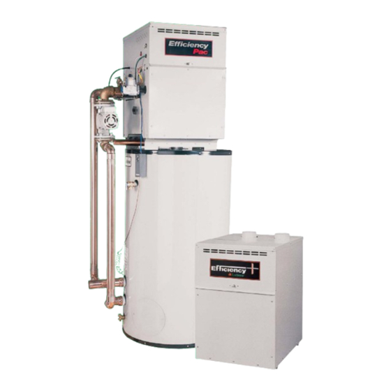
- Page 1 DESIGNER’S GUIDE EFFICIENCY+ WATER HEATER ® 1 5 0 , 0 0 0 – 3 0 0 , 0 0 0 B t u / h r...
- Page 2 The designer’s guide you are now holding has been designed to make it more convenient for you to select the perfect Lochinvar water heater for your projects and provide correct specifications for your teams. All information has been organized and presented in a succinct, easy-to-use manner, so you can use and share information confidently and with minimal effort.
-
Page 3: Table Of Contents
Table of Contents Clearances ..... .3 FIG. 12 Multiple Sidewall Direct Vent Caps ..13 Codes . -
Page 4: Codes
Lochinvar CODES In designing a hot The equipment MUST be installed in water heater system, accordance with those installation regulations pay special attention to: in effect in the local area where the installation is to be made. These MUST be carefully followed in all cases. -
Page 5: Clearances
PORT FRONT HOT WATER BACK OUTLET LEFT SIDE EW 150-300 (FIG. 1) WATER HEATER EQUIPMENT & CONTROL ORIENTATION L o c h i n v a r ’ 6 1 5 - 8 8 9 - 8 9 0 0... - Page 6 Lochinvar The equipment room MUST be provided with EXAMPLE OF properly sized openings to assure adequate SIZING FOR COMBUSTION combustion air and proper ventilation, when & VENTILATION the unit is installed with conventional venting or AIR OPENINGS sidewall venting. (WATER HEATER WITH 300,000 (FIG.
-
Page 7: Contaminants
VENTING WARNING General Vent connectors serving Vent installations for connection to gas vents or gas appliances, which chimneys should be in accordance with Part 7, operate under a “Venting of Equipment”, of the latest edition of negative vent pressure, the National Fuel Gas Code, ANSI Z223.1, or shall not be connected applicable provisions of the local building into any portion of... - Page 8 Lochinvar The vent materials and accessories, such as on the vent cap can result in a blocked flue IMPORTANT! The vent cap should firestop spacers, thimbles, caps, etc., MUST condition. Some discoloration to exterior have a minimum be installed in accordance with the building surfaces can be expected.
- Page 9 The vertical termination MUST be a minimum An interior masonry chimney, which is not NOTE: An unlined masonry of 3 feet (0.9 m) above the point of exit in the exposed to the outdoors below the roofline, chimney MUST NOT be rooftop.
-
Page 10: Conventional Venting
Lined (TABLE B) used to vent flue Chimney CONVENTIONAL VENTING, VENT CONNECTION SIZE products from this high MODEL DIAMETER efficiency appliance. EW 150 5” EW 200 5” WATER HEATER/BOILER BAROMETRIC DAMPER ON SINGLE UNIT INSTALLATION EW 250 6” EW 300 6”... - Page 11 For this type of installation, it is best to use a The sidewall or vertical roof top E+ DirectAire draft control for each water heater located on Vent combustion air supply system has specific the riser between the vent outlet and the vent material and installation requirements.
- Page 12 CONVENTIONAL VENT VENT KIT the air inlet pipe. MODEL NUMBER FLUE SIZE* INLET SIZE PART NUMBER EW 150 5” 4” SVK 3020 The point of termination for the combustion air EW 200 5” 4”...
-
Page 13: Direct Venting
This can result in incomplete combustion and DIRECT VENTING EXAMPLE OF potentially hazardous levels of carbon COMBINED AIR POSITIVE PRESSURE INLET SIZING monoxide in the flue products. A direct vent water heater uses a two pipe Two 5” air inlet pipes system, one pipe for the flue products and one (19.6 in area each) have... - Page 14 MUST be supplied by Maintain a minimum 3 foot (0.9 m) radius Lochinvar to guarantee proper operation. clearance between the combustion air inlet cap and the flue outlet cap.
-
Page 15: General Venting
MUST maintain the minimum 2 foot Vertical direct vent applications do not (0.6 m) clearance below the closest vertical flue require a vent kit to be supplied by Lochinvar. outlet if within 10 feet (3.05 m). The vent cap and air inlet cap for vertical... -
Page 16: Outdoor Installation
The cap mounts directly to the top of the water runoff drains will spill onto the water heater. heater and covers the flue outlet and combustion Lochinvar must furnish an outdoor vent kit in air inlet openings on the jacket. No additional accordance with CSA international vent piping is required. -
Page 17: Gas Supply
(TABLE G) – GAS SUPPLY PIPE SIZING EXAMPLE OF HIGH ALTITUDE Length of Pipe In Straight Feet APPLICATIONS Nominal Iron For example, if a unit’s Pipe Size, Inches input is 200,000 Btu/hr at sea level, the rated 1,400 input at 4000 feet of 2,150 1,500 1,210... -
Page 18: Low Water Temperature Delivery
(TABLE I) – REQUIRED TEMPERATURE RISE hardness. Should water hardness exceed 25 MODEL NUMBER TEMPERATURE RISE °F grains/350 TDS per gallon, consult factory EW 150 for pump sizing. EW 200 The pump chart (Table J) is based on the EW 250... -
Page 19: Electrical Requirements
MODEL CONTROLS PUMP APPROXIMATE cutoff device on models EW 150 through EW 300. NUMBER TOTAL AMPS @ 120 VAC The flow switch is installed in the outlet piping from the water heater and wired in series with the EW 150-300 11.0... - Page 20 ® E F F I C I E N C Y + W A T E R H E A T E R P I P I N G D I A G R A M S...
-
Page 21: Water Heater Piping Diagrams
W A T E R H E A T E R P I P I N G D I A G R A M S PIPING DIAGRAM SINGLE HEATER - SINGLE TANK BUILDING HOT WATER SUPPLY COLD WATER SUPPLY LOCHINVAR WATER HEATER RELIEF VALVE INLET OUTLET LOCK-TEMP... -
Page 22: Single Heater - Two Tanks
PIPING DIAGRAM SINGLE HEATER - TWO TANKS BUILDING HOT WATER SUPPLY RELIEF VALVE COLD WATER LOCHINVAR WATER HEATERS SUPPLY OUTLET LOCK-TEMP STORAGE TANK INLET DRAIN BUILDING RETURN COMMON WATER MANIFOLD PIPE SIZE FOR MULTIPLE WATER HEATER INSTALLATIONS QUANTITY OF WATER HEATERS MANIFOLD PIPE SIZE 2”... -
Page 23: Two Temperature Installation Single Heater - Single Tank
PIPING DIAGRAM TWO TEMPERATURE INSTALLATION - SINGLE HEATER - SINGLE TANK F HOT WATER SUPPLY F HOT LOCK-TEMP WATER SUPPLY STORAGE TANK LOW TEMPERATURE CHECK VALVE LOCHINVAR BUILDING RETURN WATER HEATER RELIEF VALVE MIXING VALVE INLET OUTLET DRAIN HIGH TEMPERATURE... -
Page 24: Two Heaters - Single Tank
DRAIN OUTLET OUTLET BUILDING RETURN INLET INCREASE MANIFOLD SIZE IN DIAMETER FROM TEE TO TANK INLET LOCHINVAR WATER HEATERS COMMON WATER MANIFOLD PIPE SIZE FOR MULTIPLE WATER HEATER INSTALLATIONS QUANTITY OF WATER HEATERS MANIFOLD PIPE SIZE 2” 3” ” 4”... -
Page 25: Two Heaters - Two Tanks
PIPING DIAGRAM TWO HEATERS - TWO TANKS COLD WATER SUPPLY LOCHINVAR WATER HEATERS OUTLET RELIEF BUILDING VALVE HOT WATER INLET SUPPLY LOCK-TEMP OUTLET STORAGE TANK INCREASE MANIFOLD SIZE IN DIAMETER FROM HERE TO POINT “C” DRAIN INCREASE MANIFOLD SIZE IN DIAMETER FROM HERE TO POINT “B”... -
Page 26: Multi-Stack Frame W/Water Heaters And Storage Tank
MULTI-STACK FRAME W/ WATER HEATERS AND STORAGE TANK MODEL HEATER INLET/ MANIFOLD NUMBER OUTLET SIZE PIPE SIZE EW 150-300 2” 3” LIT0665 L o c h i n v a r ’ 6 1 5 - 8 8 9 - 8 9 0 0... - Page 28 Lochinvar Corporation • 615-889-8900 / Fax 615-547-1000 www.Lochinvar.com EW-DG-03 5M-2/06-Printed in U.S.A.
Need help?
Do you have a question about the EW 150 and is the answer not in the manual?
Questions and answers