Table of Contents
Advertisement
Quick Links
Advertisement
Table of Contents

Related Manuals for Vulcan-Hart V100


Summary of Contents for Vulcan-Hart V100
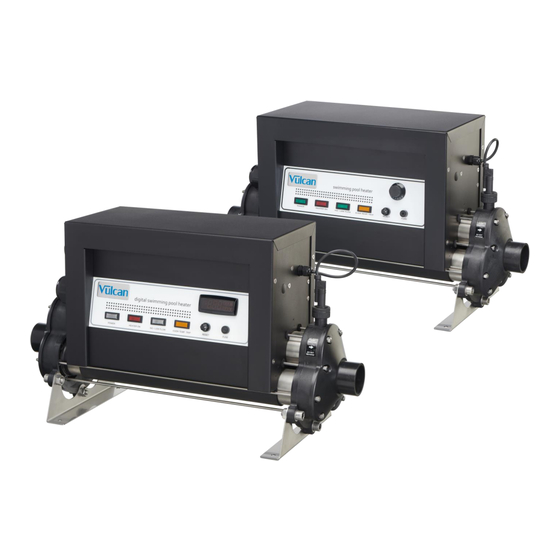
- Page 1 V100 Pool Heater Installation & Operating Manual...
-
Page 2: Table Of Contents
3.2 Water quality ........................7 3.3 THERMOSTAT INSTRUCTIONS ..................7 3.4 OPERATION PANEL ......................8 3.5 Operating the v100 heater ....................9 4. TROUBLE SHOOTING ......................9 5. MAINTENANCE ........................12 6. DISPOSAL OF ELECTRICAL AND ELECTRONIC EQUIPMENT ........12... -
Page 3: Product Overview
Introduction Thank you for purchasing a V100 electric swimming pool heater manufactured to the highest standards in England. To ensure years of trouble-free service, please read and follow these instructions for proper installation, maintenance, and use. WARNING: Failure to install the unit correctly may result in the warranty being void. -
Page 4: General Installation Instruction
2. GENERAL INSTALLATION INSTRUCTION 2.1 Mounting instruction The heater should be either installed horizontally or vertically allowing enough space for the pipe connections and wiring. It should be firmly secured using screws to a firm base or wall using the supplied wall bracket. -
Page 5: Pipe Work
2.2 Pipe work The heater should be installed at a low point in the filtration system. It should be positioned downstream of (after) the filter and upstream of (before) any dosing or other water treatment plan. (see Fig 3.). Fig 3. 2.3 Flow direction The heater can accept flow of water from only one end (please refer to flow direction labels on the products). -
Page 6: Power Requirements
2.5 Power requirements All V100 heaters are fitted with their own specification plaque that details the power requirements for the heater. Below is a table of the power requirements for the most common voltages - if your voltage is not listed please refer to the specification plaque on the product. -
Page 7: Water Quality
3.2 Water quality The water quality MUST be within the following limits: • PH: 6.8 – 8.0 • Total Alkalinity (TA): 80 – 140 ppm (parts per million) • Chloride Content MAX: 150 mg/litre • Free Chlorine: 2.0 mg/litre • Total Bromine: Max 4.5 mg/litre •... -
Page 8: Operation Panel
Item Description Function ‘P’ Button To display/Modify the required temperature ‘Down’ Button To decrease the value ‘Up’ Button To increase the value ‘U’ Button NOT USED LED-OUT Indicates that the water temperature Continuously illuminated has fallen below the required temperature Indicates that the unit is in ‘Time Delay Mode’... -
Page 9: Operating The V100 Heater
Safety Thermal Cut Out – Manual reset button (under black cover) Panel mounted fuse holder – fitted with 3-Amp glass fuse 3.5 Operating the v100 heater Upon completion of the installation, the water-circulating pump should be run to purge the system & the heater of air (i.e. - Page 10 ➢ Heater will not switch on (Red light): In most cases this will be the result of one of the following points not being met: Possible Cause 1: The temperature point set has been achieved. To confirm the increase of the temperature set, turn the dial to a value greater than the current water temperature.
- Page 11 ➢ Heater is tripping circuit breaker (MCB) after few minutes/ hours of operation: If the heater is faulty it will instantly trip the circuit breaker (MCB). The most likely causes of tripping the breaker after a period of time are: Possible Cause 1: Faulty circuit breaker.
-
Page 12: Maintenance
5. MAINTENANCE We recommend annual maintenance and cleaning of the heater to ensure proper operation. WARNING: Before performing any maintenance on the unit isolate from the main power supply. The heater should be drained, the flow tube and heating elements should be cleaned. Removing scale/sludge and any debris or blockages will extend life expectancy of the heating element(s) and avoid potential failures. - Page 13 Vulcan Pools Ltd Repairs Department Unit 11 Gunnels Wood Park Gunnels Wood Road Stevenage Hertfordshire SG1 2BH United Kingdom __________________________________________________________________________________ Customer Information: (ATTACH TO HEATER) ………………………………………………………………………………. Company Name: ………………………………………………………………………………. Contact Name: Daytime Telephone Number: ………………………………………………………………………………. ……………………………………………………………………………….. Email Address: ……………………………………………………………………………….. ……………………………………………………………………………….. Return Address: ………………………………………………………………………………..
- Page 16 11 Gunnels Wood Park, Stevenage, Herts SG1 2BH Sales@vulcanpools.co.uk www.vulcanpools.co.uk +44 (0) 1438 759192 © Copyright MANV61-EN-V100 Manual V1-01.01.2020-Vulcan...
Need help?
Do you have a question about the V100 and is the answer not in the manual?
Questions and answers