Advertisement
Quick Links
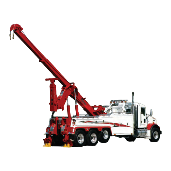
OWNER'S MANUAL
V-90 / V-100
SAFETY, SPECIFICATIONS, OPERATION, &
MAINTENANCE
NOTE: MANUAL including SPECIFICATIONS, subject to change without notice
All ratings specified are based on structural factors only,
not vehicle capacities or capabilities.
Miller Industries Towing Equipment Inc.
FORM NO. 0501128
8503 Hilltop Drive
REV. A
Ooltewah, Tennessee 37363
04 / 2011
Phone (423) 238-7227 • FAX (423) 238-7237
PRICE $25.00
Advertisement

Related Manuals for Vulcan-Hart V-90

Summary of Contents for Vulcan-Hart V-90
- Page 1 OWNER'S MANUAL V-90 / V-100 SAFETY, SPECIFICATIONS, OPERATION, & MAINTENANCE NOTE: MANUAL including SPECIFICATIONS, subject to change without notice All ratings specified are based on structural factors only, not vehicle capacities or capabilities. Miller Industries Towing Equipment Inc. FORM NO. 0501128 8503 Hilltop Drive REV.
- Page 2 LIMITED WARRANTY MILLER INDUSTRIES TOWING EQUIPMENT INC., hereinafter referred to as MILLER, warrants to the original purchaser that each new MILLER wrecker or other MILLER products will be free from defects in material and workmanship for a period of twelve (12) months from date placed in service, but in no event shall such warranty period exceed twenty-four (24) months from date of manufacture by MILLER. The purchaser must promptly notify MILLER in writing of any failure in material or workmanship. In no event shall MILLER accept such notification later than twenty-four (24) months from date of delivery or twelve (12) months from date placed in service, whichever is earlier. MILLER's obligation under this warranty, statutory or otherwise, is limited to the repair or replacement at the MILLER factory, or at a point designated by MILLER, of such part or parts as shall appear upon inspection by MILLER to be defective in material or workmanship. New or remanufactured parts will be used for any replacement at MILLER's option. This warranty is not transferable. This warranty does not obligate MILLER to bear the cost of labor or transportation charges in connection with the repair or replacement of any parts found to be defective, nor shall it apply to a product upon which repairs or alterations have been made unless authorized by MILLER. EXCEPT A S EXPRESSLY SET FORTH IN THIS WARRANTY, MILLER MAKES NO OTHER WARRANTY, EXPRESS OR IMPLIED, AND HEREBY DISCLAIMS ALL OTHER WARRANTIES INCLUDING, BUT NOT LIMITED TO, THE IMPLIED WARRANTIES OF MERCHANTABILITY AND FITNESS FOR A PARTICULAR PURPOSE. MILLER shall in no event be liable for claimed downtime, claimed loss of...
- Page 3 OWNER, USER AND OPERATOR: We appreciate your choice of our towing and recovery unit for your application. Our number one priority is user safety which is best achieved by our joint efforts. We feel that you can make a major contribution to safety if you, as the equipment owner and operator: 1.
-
Page 4: Table Of Contents
TABLE OF CONTENTS The operator must read and understand all instructions in this manual before operating the recovery unit. It is assumed that the Owner/Operator has a thorough knowledge of the accepted and lawful retrieval and towing methods as dictated by his city, county or state. - Page 5 Section I - SAFETY PRECAUTIONS Presented in the interest of safety for all towing and recovery unit operators. NOTICE You are obligated to operate your towing and recovery unit safely. You can be held legally responsible for injuries or damages resulting from unsafe operating practices.
- Page 6 Section I - SAFETY PRECAUTIONS (cont'd) 1.1 Improper use of this equipment can be dangerous! Incorrect operation can result in bodily injury to the operator and bystanders. Therefore, a thorough understanding of the "operating principles" and "operating instructions" as found in this manual is essential. 1.2 Study each job to be done.
- Page 7 Section I - SAFETY PRECAUTIONS (cont'd) MOVE IN SERVICE, AND REPLACE IF NECESSARY. SECURE ALL CAPS AND FILLER PLUGS FOR ALL SYSTEMS. 6. YOUR CLOTHING SHOULD BE RELATIVELY CLOSE FITTING. 7. ALWAYS WEAR PROTECTIVE ITEMS SUCH AS SAFETY GLASSES, GLOVES, REFLECTIVE CLOTHING AND SAFETY SHOES. 8.
- Page 8 Section I - SAFETY PRECAUTIONS (cont'd) ONLY AUTHORIZED AND TRAINED PERSONNEL SHOULD BE PERMITTED TO OPERATE THIS UNIT UNSUPERVISED. TRAINED PERSONNEL ARE THOSE WHO HAVE WORKED UNDER EXPERIENCED SUPERVISION AND HAVE PERFORMED ALL TOWING AND RECOVERY MANEUVERS, HAVE READ THE MOUNTING, OPERATING AND MAINTENANCE MANUAL, WARNINGS AND PRECAUTIONS, AND UNDERSTAND AND HAVE HAD EXPLAINED TO THEM BY THEIR EMPLOYER THE HAZARDS OF OPERATING THE...
- Page 9 Section I - SAFETY PRECAUTIONS (cont'd) SAFETY TIPS Death or serious injury can occur when working near power lines. Learn - beforehand - as much about your working area as possible. Be sure that exact locations of overhead power lines, and other obstructions or hazards are known.
- Page 10 Section I - SAFETY PRECAUTIONS (cont'd) SAFETY TIPS Don't use a towing and recovery unit that has not been properly maintained. Pay special attention to mounting bolts, cable condition, and lubrication of moving parts. Don't use damaged cables on the unit. Become familiar with the various types of cable damage and carefully inspect all cables being used in a recovery operation before...
- Page 11 Section I - SAFETY PRECAUTIONS (cont'd) SAFETY TIPS Don't expect the unit to tow loads equal to the boom rating. Ratings apply to loads imposed during recovery, with the unit properly stabilized. Don't pull a load with the unit without making absolutely sure that the winch drum clutch is FULLY engaged.
- Page 12 Section I - SAFETY PRECAUTIONS (cont'd) SAFETY TIPS Don't get under a raised vehicle or load unless it has adequate safety blocks in place. Don't exceed WORKING LIMIT ratings of cable. Use breaking strength ratings only for selecting replacement cable. Don't tie down the front end of the unit for recovery work or heavy lifts.
- Page 13 Section I - SAFETY PRECAUTIONS (cont'd) SAFETY TIPS Don't lower outboard legs or rear spades unless area under them is clear. Pay particular attention to keeping this area clear. Don't use rear spades on paved surfaces unless you are willing to accept responsibility for possible damage to such surfaces.
- Page 14 Section I - SAFETY PRECAUTIONS (cont'd) SAFETY TIPS Don't completely unwind all cable from a winch while loaded. Keep AT LEAST five wraps on the drum. Don’t operate the unit's engine f a s t e r t h a n r e c o m m e n d e d . Excessive speeds can damage PTO shafts, hydraulic pumps and winches.
- Page 15 Section I - SAFETY PRECAUTIONS (cont'd) SAFETY TIPS Don't use towing forks that are not of proper size for pick-up requirements. After you have hooked up a vehicle for towing, don't start the tow until you have double checked the hook-up, installed safety chains and released the parking brakes on the towed vehicle.
- Page 16 Section I - SAFETY PRECAUTIONS (cont'd) SAFETY TIPS Don't tow a vehicle on its front wheels if they are damaged. Don't tow a vehicle on its front wheels unless the steering wheel is secured with the front wheels straight ahead. Don't tow a vehicle without tow lights installed on the towed vehicle.
- Page 17 Section I - SAFETY PRECAUTIONS (cont'd) SAFETY TIPS Don’t move unit or extend boom where overhead power lines may be encountered. Don’t continue to wind in winch cable after the hook is against the boom end. SAFE STEERING LOAD, GVWR, GAWR, & GCWR 1.1 CHASSIS LIMITATIONS Safe operation of your equipment is limited not only by the ratings of...
- Page 18 Section I - SAFETY PRECAUTIONS (cont'd) SAFE STEERING LOAD, GVWR, GAWR, & GCWR (cont'd) 1.1 CHASSIS LIMITATIONS (cont'd) Furthermore, information may be available from your chassis manufacturer that tells you to maintain a specific amount of weight on the front axle of your chassis for safe steering. If the chassis manufacturer recommends that you should maintain more weight on your front axle than safe steering formula indicates, then you should adhere to the manufacturer’s recommendation. 2. Do not exceed the GVWR (Gross Vehicle Weight Rating) of your chassis when you are towing a load. Exceeding the GVWR of your chassis can affect its braking and handling.
- Page 19 Section I - SAFETY PRECAUTIONS (cont'd) SAFE STEERING LOAD, GVWR, GAWR, & GCWR (cont'd) 1.2 CALCULATING SAFE STEERING LOAD (cont'd) A simple formula for calculating the maximum lifted load for safe steering is shown below. It is based on the requirement for maintaining one-half the unladen steering weight. This formula has been used by the towing industry for many years and has proven reliable for determining the maximum lifted load for safe steering under good towing conditions as stated above.
- Page 20 Section I - SAFETY PRECAUTIONS (cont'd) SAFE STEERING LOAD, GVWR, GAWR, & GCWR (cont'd) 1.2 CALCULATING SAFE STEERING LOAD (cont'd) You can use pounds and inches or centimeters and kilograms in your calculations. If you use kilograms instead of pounds and centimeters instead of inches, the safe steering limits will be in kilograms. Do not mix pounds and kilograms nor inches and centimeters in the same calculation.
- Page 21 Section I - SAFETY PRECAUTIONS (cont'd) SAFE STEERING LOAD, GVWR, GAWR, & GCWR (cont'd) 1.2 CALCULATING SAFE STEERING LOAD (cont'd) FIGURE 1.2 FIGURE 1.3 3. Measure the overhang and note the distance in either inches or centimeters. Refer to Figures 1.2 & 1.3. NOTE THE TOWING DEVICE MUST BE IN ITS POSITION NORMALLY USED FOR TOWING! OTHERWISE, THE TOWING LIMITS WILL...
- Page 22 Section I - SAFETY PRECAUTIONS (cont'd) SAFE STEERING LOAD, GVWR, GAWR, & GCWR (cont'd) 1.2 CALCULATING SAFE STEERING LOAD (cont'd) 5. Multiply the result of step 4 by the wheel base. 6. Divide the result of step 5 by the overhang. The result is the maximum load that the truck can lift and maintain safe steering.
- Page 23 Section I - SAFETY PRECAUTIONS (cont'd) SAFE STEERING LOAD, GVWR, GAWR, & GCWR (cont'd) 1.2 CALCULATING SAFE STEERING LOAD (cont'd) In the above example, 7,437 pounds is the maximum safe steering load that should be lifted by the wheel lift at its usual towing position. You can calculate safe steering loads for other positions by substituting the overhang distance.
- Page 24 Section I - SAFETY PRECAUTIONS (cont'd) SAFE STEERING LOAD, GVWR, GAWR, & GCWR (cont'd) 1.3 CALCULATING GAW, GVW, & GCW (cont'd) EXAMPLE OF CALCULATING REAR AXLE GAW: This example uses numbers from the previous example to show the types of information to use: 4,250 1/2 the front axle weight + 7,437 maximum load for safe steering) + 10,000 unloaded rear axle weight 21,687 GAW of rear axle. See Figure 1.5.
- Page 25 Section I - SAFETY PRECAUTIONS (cont'd) SAFE STEERING LOAD, GVWR, GAWR, & GCWR (cont'd) 1.3 CALCULATING GAW, GVW, & GCW (cont'd) EXAMPLE OF CALCULATING GVW: This example uses numbers from the earlier example to show the types of information to use: 8,500 unloaded weight of the front axle + 10,000 unloaded weight of the rear axle + 7,437 maximum load for safe steering 25,937 GVW. Refer to Figure 1.5. Thus, the GVWR of the truck chassis used in the example should be at least 25,937 pounds.
- Page 26 Section I - SAFETY PRECAUTIONS (cont'd) SAFE STEERING LOAD, GVWR, GAWR, & GCWR (cont'd) 1.3 CALCULATING GAW, GVW, & GCW (cont'd) Remember, these are only examples. You must use the actual weights and dimensions of your tow truck when calculating GAW, GVW and GCW. Weights for most vehicles that you might encounter when towing can be obtained from various trade sources and consumer report magazines.
- Page 27 Section II - SPECIFICATIONS 2.1 Federal law requires that the final stage manufacturer, i.e., that person or company installing new equipment on a new chassis, must certify the completed vehicle by obtaining, completing and affixing to the door post on the drivers side of the vehicle, a Certification Label similar to the one shown. See Figure 2.1. FIGURE 2.1 II-1...
- Page 28 Section II - SPECIFICATIONS (cont'd) 2.2 SERIAL NUMBERS/SPECIFICATION LABELS Each Vulcan V-90 and V-100 Towing and Recovery Unit will have a Serial Number/Specification Label mounted on the upper rear tailboard. The label will display the Model Number, Serial Number, and Lift Ratings. 2.3 SPECIFICATIONS - V-90 45-Ton hydraulic recovery unit with dual hydraulic winches, 5/8" x 200' cable, hydraulic spades, 3-stage hydraulic underlift with 117" reach and power tilt, 160" C.T. modular body, pylon, lighted tool compartment, and driver's side manual controls. (a) Winches ......45,000 lbs. Planetary (b) Cable Diameter and Length (Each Drum) .
- Page 29 Section II - SPECIFICATIONS (cont'd) 2.4 SPECIFICATIONS - V-100 50-Ton hydraulic recovery unit with dual hydraulic winches, 3/4" x 250' cable, hydraulic spades, 3-stage hydraulic underlift with 144" reach and power tilt, 160" C.T. modular body, pylon, lighted tool compartment, and driver's side manual controls. (a) Winches ........50,000 lbs. (b) Cable Diameter and Length (Each Drum) .
- Page 30 Section II - SPECIFICATIONS (cont'd) 2.5 CHASSIS RECOMMENDATIONS (MINIMUM) Rear Axle GAWR (Minimum) ..... . . 38,000 lbs. Minimum GVW........50,000 lbs. C.T. (Cab to Center of Tandem) Dimension .
- Page 31 Section II - SPECIFICATIONS (cont'd) 2.7 OPTIONAL EQUIPMENT • Wireless Remote Control • Pintle Hook Attachment • Fifth Wheel Adapter • Emergency Lighting • Dress Up Packages • Heavy Duty Tire Lift • Tunnel Tool Box • Air Shift P.T.O. • Many other popular Vulcan options Note: Specifications Subject to Change without Notification. II-5...
- Page 32 NOTES...
- Page 33 Section III - OPERATIONAL FUNCTIONS RECOVERY BOOM 3.1 Your new towing and recovery unit is fully hydraulic. It receives its power by means of a Power Take-Off/Pump combination mounted to the truck transmission. Since the pump is attached to the PTO, no drive line or universal joints are required.
- Page 34 Section III - OPERATIONAL FUNCTIONS RECOVERY BOOM (cont'd) 3.3 Each function of the Recovery Boom can be controlled from the Control Stations located in the rear compartment on either side of the body. See Figures 3.3 and 3.4. FIGURE 3.3 FIGURE 3.4 III-2...
- Page 35 Section III - OPERATIONAL FUNCTIONS RECOVERY BOOM (cont'd) 3.4 The Control Handles are clearly marked as to their functions and directions. Movement of the control handles meters the flow of oil through valves to control the speed of each function. Each valve is equipped with a pressure gauge to monitor the hydraulic pressure during the operation.
- Page 36 Section III - OPERATIONAL FUNCTIONS RECOVERY BOOM (cont'd) 3.7 The Winch Air Free Spool Switches are located at the Control Station located in the left rear compartment. When activated, the winch clutch is disengaged and the drum will free spool. Refer to Figure 3.3. NOTE THE CONTROL SWITCH ON THE SWITCH PANEL IN THE TRUCK CAB MUST BE ON FOR THE FREE SPOOL SWITCHES...
- Page 37 Section III - OPERATIONAL FUNCTIONS RECOVERY BOOM (cont'd) FIGURE 3.7 STAND CLEAR WHILE OPERATING REAR SPADES. 3.10 Safety Chains are located at the tailboard of the subframe. See Figure 3.8. III-5...
- Page 38 Section III - OPERATIONAL FUNCTIONS RECOVERY BOOM (cont'd) FIGURE 3.8 USE SAFETY CHAINS ON ALL TOWING AND LIFTING APPLICATIONS. III-6...
- Page 39 Section IIIA - OPERATIONAL FUNCTIONS UNDERLIFT 3A.1 Your new Vulcan Underlift is totally hydraulic. It receives its power by means of a Power Take-Off/Pump combination attached to the vehicle transmission. Since the pump is attached directly to the PTO, no drive line or universal joints are required.
- Page 40 Section IIIA - OPERATIONAL FUNCTIONS UNDERLIFT (cont'd) FIGURE 3A.2 FIGURE 3A.3 3A.3 The Control Handles are clearly identified as to functions and directions. Movement of the control handles meters the flow of oil through valves to control the speed of each function. Each valve is equipped with a pressure gauge to monitor the hydraulic pressure during the operations. IIIA-2...
- Page 41 Section IIIA - OPERATIONAL FUNCTIONS UNDERLIFT (cont'd) 3A.4 The Underlift is elevated, lowered, extended and retracted by means of double-acting cylinders. The boom can be elevated or extended under either "LOAD" or "NO-LOAD" conditions. 3A.5 REMOTE CONTROL UNIT (a) The remote control unit (Power Pal) is located and plugged into the power receptacle in the rear body compartment. Refer to Figure 3A.3.
- Page 42 Section IIIA - OPERATIONAL FUNCTIONS UNDERLIFT (cont'd) FIGURE 3A.4 IIIA-4...
- Page 43 Section IV - OPERATING INSTRUCTIONS RECOVERY BOOM 4.1 For reasons of safety, it is important that the Owner(s) and Operator(s) become thoroughly familiar with the controls and functions of the recovery unit before attempting any operation. 4.2 HYDRAULIC WINCHES (a) DO NOT fasten the winch hook directly to any vehicle. (b) DO NOT wrap the winch cable around any object.
- Page 44 Section IV - OPERATING INSTRUCTIONS RECOVERY BOOM (cont'd) NOTE THE PRESSURE REGULATOR FOR THE CABLE TENSIONERS MUST BE ADJUSTED TO MAINTAIN 40 TO 50 POUNDS OF PRESSURE AT ALL TIMES TO PREVENT FOULING LINE DURING MANUAL PAYOUT. SEE FIGURE 4.1. FIGURE 4.1 4.5 BOOM ELEVATION &...
- Page 45 Section IV - OPERATING INSTRUCTIONS RECOVERY BOOM (cont'd) 4.5 BOOM ELEVATION & EXTENSION (cont'd) TO AVOID DAMAGE TO WINCHES, CABLES, OR BOOM, MAKE CERTAIN WINCH CABLES ARE FREE AND HAVE SUFFICIENT SLACK TO ALLOW BOOM TO EXTEND! 4.6 REAR SPADES (a) The rear spades are for use when lifting heavy loads.
- Page 46 Section IV - OPERATING INSTRUCTIONS RECOVERY BOOM (cont'd) 4.6 REAR SPADES (cont'd) STAND CLEAR WHILE OPERATING REAR SPADES! USE SAFETY CHAINS ON ALL TOWING AND LIFTING APPLICATIONS! IV-4...
- Page 47 Section IVA - OPERATING INSTRUCTIONS UNDERLIFT 4A.1 For reasons of safety, it is important that the Owner(s) and Operator(s) become thoroughly familiar with its controls, components and load requirements before attempting any operation. 4A.2 PREPARING TO LOAD VEHICLE (a) Align unit with vehicle to be towed. (b) Reduce truck’s engine to an idle, and apply parking brake.
- Page 48 Section IVA - OPERATING INSTRUCTIONS UNDERLIFT (cont'd) 4A.3 UNDERLIFT OPERATION (cont'd) FIGURE 4A.1 (c) Remove and stow the Underlift Centering Pin immediately after unfolding the underlift boom. See Figure 4A.2. FIGURE 4A.2 IVA-2...
- Page 49 Section IVA - OPERATING INSTRUCTIONS UNDERLIFT (cont'd) 4A.3 UNDERLIFT OPERATION (cont'd) THE UNDERLIFT CENTERING PIN MUST BE REMOVED DURING ALL UNDERLIFT TOWING OPERATIONS. (d) At this point, you must determine which type lift you are going to use for towing: FORK LIFT; SPRING LIFT; AXLE LIFT; TRUCK WHEEL LIFT;...
- Page 50 Section IVA - OPERATING INSTRUCTIONS UNDERLIFT (cont'd) 4A.3 UNDERLIFT OPERATION (cont'd) FIGURE 4A.3 IVA-4...
- Page 51 Section IVA - OPERATING INSTRUCTIONS UNDERLIFT (cont'd) 4A.4 AXLE LIFT (USING FORKS) NOTE STEPS A THRU D ARE NOT REQUIRED IF AXLE IS HIGH ENOUGH TO PERMIT EXTENSION OF CROSSBAR UNDER AXLE WITH FORKS INSTALLED. (a) Press "OUT" button and extend the Underlift Boom (without forks attached) until crossbar is centered with front axle of disabled vehicle.
- Page 52 Section IVA - OPERATING INSTRUCTIONS UNDERLIFT (cont'd) 4A.4 AXLE LIFT (USING FORKS) (cont'd) FIGURE 4A.4 FIGURE 4A.5 IVA-6...
- Page 53 Section IVA - OPERATING INSTRUCTIONS UNDERLIFT (cont'd) 4A.4 AXLE LIFT (USING FORKS) (cont'd) (h) Select forks suited for job and install in fork adapters on crossbar. See Figure 4A.6. FIGURE 4A.6 (i) Press "OUT" button to extend boom until forks are under axle. NOTE TILT BOOM DOWN, AS REQUIRED, USING "TILT DOWN"...
- Page 54 Section IVA - OPERATING INSTRUCTIONS UNDERLIFT (cont'd) 4A.4 AXLE LIFT (USING FORKS) (cont'd) NOTE RETAINING PINS MUST BE IN PLACE DURING ALL TOWING APPLICATIONS. (l) Press "TILT UP" button and bring forks into contact with axle. If necessary, press "UP" button to raise boom. (m) Attach safety chains around axle, crossbar tube and forks as shown in Figure 4A.7.
- Page 55 Section IVA - OPERATING INSTRUCTIONS UNDERLIFT (cont'd) 4A.4 AXLE LIFT (USING FORKS) (cont'd) (n) Press "UP" button to raise vehicle to desired height for towing. (o) Remove blocks if previously placed under front wheels. (p) Press "IN" button and pull vehicle in as far as possible while still maintaining a safe turning radius.
- Page 56 Section IVA - OPERATING INSTRUCTIONS UNDERLIFT (cont'd) 4A.5 SPRING LIFT (cont'd) (d) Position fork adapters in desired position on crossbar. (Fork adapters may be placed in any of four (4) positions). Place retaining pins in holes in crossbar and secure with lynch pins. Refer to Figures 4A.4 and 4A.5.
- Page 57 Section IVA - OPERATING INSTRUCTIONS UNDERLIFT (cont'd) 4A.5 SPRING LIFT (cont'd) FIGURE 4A.9 (h) Tighten "T" handles on adapters. Make sure retaining pins at ends of crossbar are secure. (i) Press "UP" button and raise boom until brackets are properly seated under springs at front spring hanger brackets.
- Page 58 Section IVA - OPERATING INSTRUCTIONS UNDERLIFT (cont'd) 4A.5 SPRING LIFT (cont'd) NOTE MAKE SURE THERE IS ENOUGH SLACK IN SAFETY CHAINS TO PERMIT TURNING. (l) Press "UP" button and raise vehicle to desired height for towing. (m) Using "IN" button, pull vehicle in as far as possible while still maintaining a safe turning radius.
- Page 59 Section IVA - OPERATING INSTRUCTIONS UNDERLIFT (cont'd) 4A.6 TRUCK WHEEL LIFT (cont'd) FIGURE 4A.10 (d) Extend boom to maximum stroke and then retract approximately 3". (e) Disengage PTO and back wrecker until crosstubes are firmly against tires of truck to be towed. Take wrecker out of gear, apply parking brake and re-engage PTO.
- Page 60 Section IVA - OPERATING INSTRUCTIONS UNDERLIFT (cont'd) 4A.6 TRUCK WHEEL LIFT (cont'd) (f) Insert adjustment tubes into outer crosstubes. Insert retainer pins into keyhole slots on outer crosstube and rotate 180° to lock in place. See Figure 4A.12. FIGURE 4A.12 (g) Install tire supports onto adjustment tubes and slide in until firmly against back of tire.
- Page 61 Section IVA - OPERATING INSTRUCTIONS UNDERLIFT (cont'd) 4A.6 TRUCK WHEEL LIFT (cont'd) FIGURE 4A.13 (h) Before lifting dual axle vehicles from the rear, install 5/16" high test tow chains on both sides of vehicle to be towed. Attach one end of chain around forward axle, over frame rail and back around axle.
- Page 62 Section IVA - OPERATING INSTRUCTIONS UNDERLIFT (cont'd) 4A.6 TRUCK WHEEL LIFT (cont'd) FIGURE 4A.14 (k) Attach tiedown strap hooks to rear tire support. See Figure 4A.15. FIGURE 4A.15 IVA-16...
- Page 63 Section IVA - OPERATING INSTRUCTIONS UNDERLIFT (cont'd) 4A.6 TRUCK WHEEL LIFT (cont'd) (l) Route tiedown strap across top of tire and insert into ratchet on outer crosstube and tighten. See Figure 4A.16. FIGURE 4A.16 (m) Wrap horizontal strap around tire and attach to tie down strap as shown in Figures 4A.17 and 4A.18.
- Page 64 Section IVA - OPERATING INSTRUCTIONS UNDERLIFT (cont'd) 4A.6 TRUCK WHEEL LIFT (cont'd) FIGURE 4A.18 (n) Repeat tiedown strap procedures on opposite side of vehicle to be towed. USE SAFETY CHAINS ON ALL TOWING AND LIFTING APPLICATIONS. (o) Press "IN" button and pull vehicle in as far as possible while still maintaining a safe turning radius.
- Page 65 Section IVA - OPERATING INSTRUCTIONS UNDERLIFT (cont'd) 4A.6 TRUCK WHEEL LIFT (cont'd) NOTE MAKE SURE THERE IS ENOUGH SLACK IN SAFETY CHAINS TO PERMIT TURNING. (q) Stow remote control unit and give hookup a final check before commencing towing operation. 4A.9 KINGPIN PLATE The Kingpin Plate is used on dropped trailers. (a) Slide keyhole slot in kingpin plate over trailer kingpin.
- Page 66 Section IVA - OPERATING INSTRUCTIONS UNDERLIFT (cont'd) 4A.8 KINGPIN PLATE (cont'd) USE SAFETY CHAINS ON ALL TOWING AND LIFTING APPLICATIONS. IVA-20...
- Page 67 Section V - MAINTENANCE A daily vehicle inspection should be performed every day the unit is in use. 5.1 The continued operation of your towing and recovery unit is largely dependent upon strict adherence to a properly scheduled preventive maintenance program. To help you in this program, has provided the following information regarding lubrication, preventive maintenance, hydraulic system and safety devices care.
- Page 68 Section V - MAINTENANCE (cont'd) 5.3 LUBRICATION & PREVENTIVE MAINTENANCE (cont'd) 3. Cylinders 4. Boom End Fittings 5. Controls 6. Hydraulic Oil Filters 7. Oil Reservoir 8. Lights and Wiring 9. Winches 10. Pivot Bearing Surfaces and Pins (See Lubrication Charts, page V-9 thru V-13.) (b) Check hydraulic oil level in reservoir and fill to center of sight gauge with Multi-Purpose Automatic Transmission Fluid, formally known as MERCON / DEXRON III. Hydraulic oil should be replaced...
- Page 69 Section V - MAINTENANCE (cont'd) 5.3 LUBRICATION & PREVENTIVE MAINTENANCE (cont'd) (g) Grease boom slide pads with grease with grease fittings located on top of outer boom at heel end second stage only. (h) Check oil level of winches and fill to level of oil plug located in side plate of gear housing Use SAE 140 general purpose gear oil. Lubricate grease fittings on clutches. (i) Lubricate winch cables using an oily rag while respooling onto drum. Other special cable lubricants are available which have better penetrating qualities.
- Page 70 Section V - MAINTENANCE (cont'd) 5.5 CARE OF HYDRAULICS IN COLD CLIMATE When the towing and recovery unit are used in seasonal cold climate regions (+20° F and below), the viscosity of the normally recommended oil may increase to the point where it adversely affects hydraulic functions during starting and warm-up.
- Page 71 Section V - MAINTENANCE (cont'd) LUBRICATION CHART...
-
Page 72: Maintenance Record
Section V - MAINTENANCE (cont'd) MAINTENANCE RECORD DATE MECHANIC WEEKLY* MONTHLY QUARTERLY SERVICE PERFORMED *IMPORTANT: HYDRAULIC HOSES AND CABLES SHOULD BE INSPECTED WEEKLY FOR SIGNS OF ABRASION. - Page 73 Section V - MAINTENANCE (cont'd) MAINTENANCE RECORD DATE MECHANIC WEEKLY* MONTHLY QUARTERLY SERVICE PERFORMED *IMPORTANT: HYDRAULIC HOSES AND CABLES SHOULD BE INSPECTED WEEKLY FOR SIGNS OF ABRASION.
- Page 74 Section V - MAINTENANCE (cont'd) MAINTENANCE RECORD DATE MECHANIC WEEKLY* MONTHLY QUARTERLY SERVICE PERFORMED *IMPORTANT: HYDRAULIC HOSES AND CABLES SHOULD BE INSPECTED WEEKLY FOR SIGNS OF ABRASION.
- Page 75 Section V - MAINTENANCE (cont'd) MAINTENANCE RECORD DATE MECHANIC WEEKLY* MONTHLY QUARTERLY SERVICE PERFORMED *IMPORTANT: HYDRAULIC HOSES AND CABLES SHOULD BE INSPECTED WEEKLY FOR SIGNS OF ABRASION.
- Page 76 NOTES...
-
Page 77: Section Vl - Schematics
Section VI - SCHEMATICS ELECTRICAL VI-1... -
Page 78: Hydraulic System
Section VI - SCHEMATICS HYDRAULIC SYSTEM VI-2... -
Page 79: Pneumatic System
Section VI - SCHEMATICS (cont'd) PNEUMATIC SYSTEM VI-3... -
Page 80: Electrical Remote Control System
Section VI - SCHEMATICS (cont'd) ELECTRICAL REMOTE CONTROL SYSTEM VI-4... - Page 81 NOTES...
- Page 82 Miller Industries Towing Equipment Inc. 8503 Hilltop Drive • Ooltewah, Tennessee 37363 • (423) 238-7227 www.millerind.com...
Need help?
Do you have a question about the V-90 and is the answer not in the manual?
Questions and answers