Table of Contents
Advertisement
Quick Links
Advertisement
Table of Contents

Related Manuals for cyber Switching CSE2 Series


Summary of Contents for cyber Switching CSE2 Series
- Page 1 Electric Vehicle AC Charger CSE2 Series - User Manual...
-
Page 2: Important Safety Instructions
WARNING – This manual contains important instructions for Models: 1) Lisez toutes les instructions avant d'utiliser ce produit. CSE2 series that shall be followed during installation, operation and maintenance of the unit. 2) Cet appareil doit être surveillé lorsqu'il est utilisé à proximité d'enfants. -
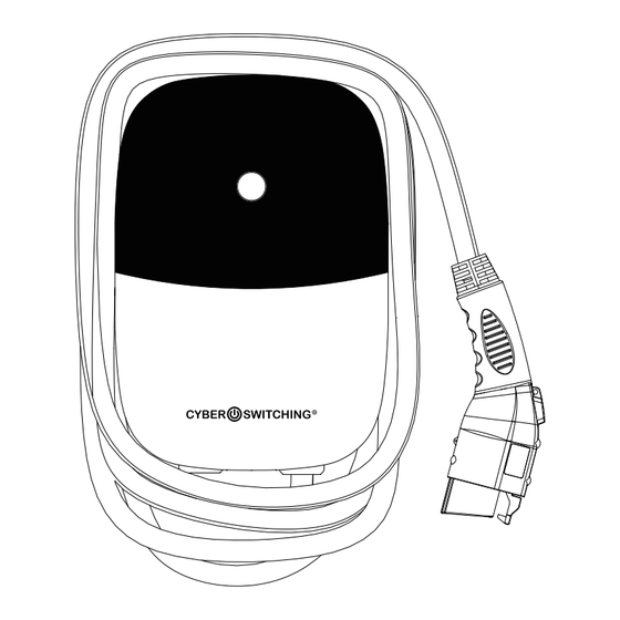
Page 3: Basic Interface
USER MANUAL USER MANUAL 2. Basic Interface WARNING This device complies with part 15 of the FCC Rules. Operation is subject to the following two conditions: This device may not cause harmful interference, and this device must accept any interference LED Light received, including interference that may cause undesired operation. -
Page 4: Design Standard
USER MANUAL USER MANUAL 3. Dimensions 4. Design Standard 3.9" UL 2594: Electric Vehicle Supply Equipment UL 2231-1: Personnel Protection Systems for Electric Vehicle (EV) Supply Circuits: General 9.8" Requirements UL 2231-2: Personnel Protection Systems for Electric Vehicle (EV) Supply Circuits: Particular Requirements for Protection Devices for Use in Charging Systems UL 2251: Plugs, Receptacles and Couplers for Electric Vehicles UL 62: Flexible Cords and Cables... -
Page 5: Specification
USER MANUAL USER MANUAL 5. Specification 6. Status Description of the Charger Indication Light Model Name CSE2 Version Rated Input Voltage 200-240 VAC Standby - Blue Light Rated Output Current 16/32/40/48A/70A/80A The READY light stays steady in AC Power Frequency 60 Hz standby mode. -
Page 6: Product Name
7. Packing List 8 Installation Instructions Electric Vehicle AC Charger CSE2 Series - User Manual 8.1 Safety Requirements • Be sure to preview the user manual and ensure local building and electrical codes are reviewed before installing the AC charger. - Page 7 USER MANUAL USER MANUAL 8.2 Wiring For safe use of electricity, please add circuit breaker protection in the input part of charging pile. Connect the L1 lead to the grid L1, connect the L2 lead to the grid L2, GROUNDING INSTRUCTIONS connect the PE lead to the grid PE (for all Version).
-
Page 8: Tools And Materials Required
USER MANUAL USER MANUAL 8.3 Tools and Materials Required 8.4 Wall-Mounted Bracket Installation Step 1: Tools required before installing the Wall-Mounted charger, gather the following tools: • Set the positions of the 4 screw holes and drill them, with a diameter of 8mm and •... -
Page 9: Operating Procedures
USER MANUAL USER MANUAL 9. Operation Instuctions Step 3: Fix two M5 screws to complete the installation. 9.1 Operating Procedures User authorization Connect to Vehicle Charging Inlet Charging Message Charging completed 9.2 Operating Steps 9.2.1 Operating Steps with Plug and Charge Step 1 / Standby Mode After power-on, blue light (READY), green light (CHARGE) and red light (FAULT) all lit. - Page 10 USER MANUAL USER MANUAL 9.2.2 Operating Steps with RFID Step 1 / Standby Mode After power-on, blue light (READY), green light (CHARGE) and red light (FAULT) all lit. Enter standby mode and the blue light (READY) is steady on. CHARGE READY Step 4 / Charging Finished Step 2 / Tap the RFID Card...
-
Page 11: Error And Warning Message
USER MANUAL USER MANUAL 9.3 Error and Warning Message Status Remark Input OVP 1 flashes followed by 3 sec pause Auto Recover Input UVP 2 flashes followed by 3 sec pause Auto Recover Output OCP 3 flashes followed by 3 sec pause Auto Recover 4 flashes followed by 3 sec pause Auto Recover... -
Page 12: Maintenance And Repair
The warranty period for this charger is two years. • After the event of any repair or maintenance under the warranty period, if there is no purchase to extend the warranty service, Cyber Switching shall provide a three-month warranty period for any subsequent paid repair work.
Need help?
Do you have a question about the CSE2 Series and is the answer not in the manual?
Questions and answers