
Subscribe to Our Youtube Channel
Related Manuals for Ferroli EGEA TECH 200 LT


Summary of Contents for Ferroli EGEA TECH 200 LT
- Page 1 EGEA TECH 200 LT - 260 LT - 200 LT-S - 260 LT-S UK version EN - USER, INSTALLATION AND MAINTENANCE MANUAL...
-
Page 2: Table Of Contents
EGEA TECH 200 LT - 260 LT -200 LT-S - 260 LT-S UK version SUMMARY SAFETY WARNINGS ..................4 HANDLING AND TRANSPORT ..............36 GENERAL INFORMATION ................9 “G3 KIT 24L” ACCESSORY .................37 RECIPIENTS OF THE MANUAL ..............9 HANDLING OF PACKAGING .................37 GUIDE TO THE MANUAL ................10 UNPACKING ....................37 2.2.1 Supply and storage of the manual ............10 RECEIPT ......................37... - Page 3 200 and 260 liter tanks and can In the event of loss of or damage to this manual, another copy be prepared with integration from a solar heating panel. can be downloaded from the website www.ferroli.com by se- lecting the purchased product. Version...
-
Page 4: Safety Warnings
ATTENTION complied with. chased product. The equipment must be installed... - Page 5 EGEA TECH 200 LT - 260 LT -200 LT-S - 260 LT-S UK version For models including a heat mandatory that installation complies with part exchanger (solar coil), the circu- G3 of the Building Regulations. it must not exceed 1.0 MPa (10 ATTENZIONE ATTENTION For that the unit is factory...
- Page 6 EGEA TECH 200 LT - 260 LT -200 LT-S - 260 LT-S UK version The device must be installed in DO NOT TAMPER WITH THE compliance with the regulations POWER CORD. on electrical systems in force in If the power supply cable is dam- ATTENTION ATTENTION the country of installation.
- Page 7 An incorrect command can put yourself and others at risk and In the absence of such written authorisation, the use is to be cause material damage. considered “improper use”; therefore FERROLI declines all • Read these instructions and all complementary documen- responsibility in relation to any damage caused to things or tation carefully.
- Page 8 EGEA TECH 200 LT - 260 LT -200 LT-S - 260 LT-S UK version ► DANGER OF DEATH DUE TO Any intervention on the ap- CHANGES TO THE PRODUCT OR pliance, including disposal, THE INSTALLATION ENVIRONMENT must be carried out by quali- •...
-
Page 9: General Information
EGEA TECH 200 LT - 260 LT -200 LT-S - 260 LT-S UK version RECIPIENTS OF THE MANUAL INSTRUCTIONS FOR: It is intended for the specialist installer (installers - maintenance technicians) and the end user. To distinguish the content of the manual based on the charac- EXPERT TECHNICIAN / teristics of the recipient (user and expert technician), the instruc- USER... -
Page 10: Guide To The Manual
For the correct use of the device, the technical reference is in digital version, which can be downloaded from the website the “USE, INSTALLATION AND MAINTENANCE MANUAL” www.ferroli.com by selecting the purchased product. supplied with it. The manual must be kept for future reference until dismantling. -
Page 11: Compliance With European Regulations
EGEA TECH 200 LT - 260 LT -200 LT-S - 260 LT-S UK version COMPLIANCE WITH EUROPEAN DISCLAIMER OF LIABILITY REGULATIONS The conformity of these operating instructions with the hard- ware and the software has been carefully checked. There may, This heat pump is a product intended for domestic use in com- however, be some differences, therefore, we do not assume pliance with the following European directives:... -
Page 12: General And Control Panel Cleaning
EGEA TECH 200 LT - 260 LT -200 LT-S - 260 LT-S UK version CHECK OF THE DEVICE 3.2.1 General and control panel cleaning Equipment to be Periodicity: Periodicity: used MONTHLY Soft and dry cloth (or in conditions of YEARLY EXPERT TECHNICIAN USER / MANUFACTURER'S... -
Page 13: Description Of The User Interface
EGEA TECH 200 LT - 260 LT -200 LT-S - 260 LT-S UK version DESCRIPTION OF THE USER INTERFACE The user interface of this model of water heater con- sists of four capacitive keys and an LED display. As soon as the water heater is powered, the four keys and all the icons on the display are backlit, then the display firmware version is shown on the display. -
Page 14: Standby
EGEA TECH 200 LT - 260 LT -200 LT-S - 260 LT-S UK version 3.5.3 Standby 3.6.4 VENTILATION In standby mode, the wording Stb is shown on the display. FAn ” is shown on the display In this mode, the heat pump is off, but all the auxiliary functions With this mode only the fan inside the appliance is used and (photovoltaic, smart grid, solar thermal, anti-legionella) and the it is useful if you want to recirculate the air in the installation... -
Page 15: Cascade Functionality
EGEA TECH 200 LT - 260 LT -200 LT-S - 260 LT-S UK version CASCADE FUNCTIONALITY HOW TO ACCESS THE USER AND INSTAL- LER MENU The term cascade is intended to indicate a group of water he- aters that work together, within which only one Master and se- In addition to the possibility of changing the set-point, veral slaves are identified. -
Page 16: Using The Keys While Navigating In The Menus
EGEA TECH 200 LT - 260 LT -200 LT-S - 260 LT-S UK version 3.9.1 Using the keys while navigating in the menus ming is disabled, default value). To activate time band programming, use the “+” and “-” keys to bring the value to “1”. Action Symbol Within a menu or submenu... -
Page 17: Fan Menu - Fan And Silent Mode Setting
EGEA TECH 200 LT - 260 LT -200 LT-S - 260 LT-S UK version 3.9.5 ENERGY MONITORING Then press the “SET” key for 3 secon- ds to confirm (a beep will confirm the modifica- The Energy Monitoring function al- tion) or the “ON/OFF” key to exit the menu. -
Page 18: Rst Menu - Reset
EGEA TECH 200 LT - 260 LT -200 LT-S - 260 LT-S UK version NOTA: Value Description Unit of measure Level * : for the correct reading of this parameter, the va- Et3 * Weekly thermal energy kWh / 10 * U / I lue resulting from the 3 screens must be divided by 10. -
Page 19: Hi Menu - Electric Heater Setting
EGEA TECH 200 LT - 260 LT -200 LT-S - 260 LT-S UK version 3.9.8 HI menu - ELECTRIC HEATER SETTING “SET” key the value “P01” will appear. Unit of Parame- Unit of Value Description default min Level Description default min max Level measure measure... -
Page 20: Sg Menu - Smart Grid Functionality
EGEA TECH 200 LT - 260 LT -200 LT-S - 260 LT-S UK version setpoint=50°C the photovoltaic setpoint will not be 50+30=80 Unit of Value Description default min Level measure but 75°C. Enable Smart Grid function (0=disabled, 1=enabled) Setpoint offset for operating state 3 °C When the PHOTOVOLTAIC function is enabled, the symbol ap- Level: U=user menu - I=installer menu... -
Page 21: Rec Menu - Recirculation Pump Setting
EGEA TECH 200 LT - 260 LT -200 LT-S - 260 LT-S UK version panel circulator remains on 14 days (changeable default value) and to activate after mid- L04: represents the duration of the cycle in which the solar night on the fourteenth day. panel circulator remains off L05: if the panel temperature exceeds this value, the SOLAR ATTENTION: the 14-day waiting time cycle may not even be... -
Page 22: Cas Menu - Cascata
EGEA TECH 200 LT - 260 LT -200 LT-S - 260 LT-S UK version appears on the display according to the following logic: NOTE: value parameter identi- Behavior Description Active mode fies the position of the Slave inside the cascade. ANTI-LEGIONELLA enabled The unit continues to work in the mode on with... -
Page 23: More Features
EGEA TECH 200 LT - 260 LT -200 LT-S - 260 LT-S UK version Example of displaying the serial number “G000083277” 3.10 More features In this example the display is carried out by combining all the values found in the 5 screens: 3.10.1 Defrost function •... -
Page 24: Control Of The Device Via App
12 ing the icon as indicated above. User registration To use the"Ferroli Home" application for the first time, user re- 3. Privacy Policy gistration is required: create a new account → enter the mobile phone number/e-mail address → enter the verification code and set the password →... - Page 25 EGEA TECH 200 LT - 260 LT -200 LT-S - 260 LT-S UK version 4. Terms and conditions of use 6. Pin fig. 14 fig. 16 5. Password 7. Registration completed fig. 15 fig. 17 cod. 3540000830 - Rev. 03 / 04 - 01/2024...
- Page 26 EGEA TECH 200 LT - 260 LT -200 LT-S - 260 LT-S UK version 8. Blank homepage 10. Camera permission. fig. 18 fig. 20 9. Association method 11. Data matrix fig. 19 fig. 21 cod. 3540000830 - Rev. 03 / 04 - 01/2024...
- Page 27 EGEA TECH 200 LT - 260 LT -200 LT-S - 260 LT-S UK version 12. Device type and model. 14. Bluetooth activation and authentication PIN generation. fig. 22 fig. 24 15. Bluetooth search. 13. Smartphone bluetooth permission fig. 25 fig. 23 cod.
- Page 28 EGEA TECH 200 LT - 260 LT -200 LT-S - 260 LT-S UK version 16. Bluetooth devices nearby 18. Connection to the wifi network fig. 26 fig. 28 Select the device whose name starts with BT-1955 19. Wifi info. 17. 3-digit PIN fig.
- Page 29 EGEA TECH 200 LT - 260 LT -200 LT-S - 260 LT-S UK version 20. WI-FI Incorrect data. 22. Connecting. fig. 30 fig. 32 21. Connecting 23. Nickname fig. 31 fig. 33 cod. 3540000830 - Rev. 03 / 04 - 01/2024...
- Page 30 EGEA TECH 200 LT - 260 LT -200 LT-S - 260 LT-S UK version 24. End of association. 26. Homepage fig. 34 fig. 36 25. Plant information 27. Login fig. 35 fig. 37 cod. 3540000830 - Rev. 03 / 04 - 01/2024...
-
Page 31: Faults/Protection
EGEA TECH 200 LT - 260 LT -200 LT-S - 260 LT-S UK version 3.12 FAULTS/PROTECTION This device has a self-diagnosis system that covers some pos- If one or more of the above sible faults or protections from anomalous operating conditions faults occur, contact the through: detection, signalling and adoption of an emergency manufacturer's technical as-... -
Page 32: Troubleshooting
EGEA TECH 200 LT - 260 LT -200 LT-S - 260 LT-S UK version 3.13 TROUBLESHOOTING If the equipment is not working properly, without any alarm sig- naling, before contacting the manufacturer’s technical assis- tance service, it is advisable to carry out the following. Malfunction Recommended action •... -
Page 33: General Information
EGEA TECH 200 LT - 260 LT -200 LT-S - 260 LT-S UK version GENERAL INFORMATION INSTRUCTIONS FOR: PLATE DATA Read the data plate affixed to the device and check that the user manual corresponds to the model indicated. EXPERT TECHNICIAN / USER MANUFACTURER'S TECHNICAL ASSISTANCE... -
Page 34: Identification Plates Of The Main Elements
EGEA TECH 200 LT - 260 LT -200 LT-S - 260 LT-S UK version Symbol Definition Do not tamper with the data plate in any way. GENERIC PROHIBITION. ATTENTION Symbol used to identify the prohibition of the prescribed description. PROHIBITION In the event of a request for information or technical assis- tance, it is necessary to specify, in addition to the model and WEIGHT. -
Page 35: Glossary Of Terms
EGEA TECH 200 LT - 260 LT -200 LT-S - 260 LT-S UK version PERSONAL PROTECTIVE EQUIPMENT Symbol Definition The clothes worn by people who work or carry out maintenance It indicates the position on the transport work must comply with the essential safety requirements de- package where the clamps must be fined by the laws in force in the country in which it is installed. -
Page 36: Residual Risks
EGEA TECH 200 LT - 260 LT -200 LT-S - 260 LT-S UK version RESIDUAL RISKS Position allowed only for the last km The design was carried out in order to ensure the essential safety requirements for the operator in charge and for the end user. -
Page 37: G3 Kit 24L" Accessory
EGEA TECH 200 LT - 260 LT -200 LT-S - 260 LT-S UK version “G3 KIT 24L” ACCESSORY It is mandatory that the installation complies with part G3 of the Building Regulations. For that the unit is factory equipped with a T/P safety relief valve (set = 90°C/7bar) and is supplied with a G3 kit composed by: The packaged device... -
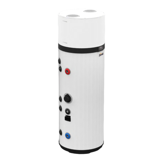
Page 38: Construction Features
EGEA TECH 200 LT - 260 LT -200 LT-S - 260 LT-S UK version CONSTRUCTION FEATURES fig. 43 Legend heat pump User interface Steel casing Electrical heater Magnesium anode Ventilation air inlet Ø 160mm Ventilation air outlet Ø 160mm Cold water inlet connection Ø 1”G Hot water outlet connection Ø... -
Page 39: Dimensional Data
EGEA TECH 200 LT - 260 LT -200 LT-S - 260 LT-S UK version DIMENSIONAL DATA fig. 45 Legend on previous page. fig. 47 Ø Legend on previous page.. MODEL 200 LT-S 260 LT-S 200 LT 260 LT 1162 1162 1142 1427 1142... -
Page 40: Technical Features
EGEA TECH 200 LT - 260 LT -200 LT-S - 260 LT-S UK version TECHNICAL FEATURES U.m. Models 200 LT 260 LT 200 LT-S 260 LT-S Voltage supplie 230Vac-50Hz Tank water content - Vnom Maximum inlet water pressure Empty weight General data Operating weight Dimensions (fxh) -
Page 41: Installation And Commissioning
EGEA TECH 200 LT - 260 LT -200 LT-S - 260 LT-S UK version INSTALLATION AND LIMITS OF USE COMMISSIONING This product has not been de- signed, nor is it intended as such, Product installation, commissioning and maintenance to be used in hazardous envi- must be carried out by qualified and authorised per- ATTENTION ronments according to Directive... -
Page 42: Environmental Conditions For Operation
EGEA TECH 200 LT - 260 LT -200 LT-S - 260 LT-S UK version 9.3.1 Environmental conditions for operation NB: In the design and construc- tion phase of the plants, the ap- The device cannot operate in rooms classified as environ- plicable local regulations and OBLIGATION provisions must be complied... -
Page 43: Floor Fixing
EGEA TECH 200 LT - 260 LT -200 LT-S - 260 LT-S UK version For the required ducting installations, please refer to “9.6 AER- AULIC CONNECTIONS” on page 44. ≥300 mm ≥ 300 mm* The room must also be:: ≥ 400 mm if the display faces •... -
Page 44: Aeraulic Connections
EGEA TECH 200 LT - 260 LT -200 LT-S - 260 LT-S UK version Mandatory air inlet D.160 mm Internal compartment fig. 52- Fixing to the floor AERAULIC CONNECTIONS In many images of this document the position of the air ducts are schematized at the top and bot- ATTENZIONE tom, in reality for the purposes... -
Page 45: Cascade System Aeraulic Connections
EGEA TECH 200 LT - 260 LT -200 LT-S - 260 LT-S UK version The negative pressure can cause the return of Install each air duct making sure that: exhaust gases into the room. • It does not weigh down on the equipment. •... -
Page 46: Special Installation
EGEA TECH 200 LT - 260 LT -200 LT-S - 260 LT-S UK version Mandatory air D [mm] inlet D.160 mm Nota: Over 4 units (max 8), consider two separate ducts referring to the diameters in the table relating to the number of units con- Damper "A"... -
Page 47: Hydraulic Connections
EGEA TECH 200 LT - 260 LT -200 LT-S - 260 LT-S UK version Hydraulic connections Connection the piping for domestic hot water Connect the cold water supply line and the outlet line to the appropriate connection points (fig. 60). The table below gives the characteristics of the connection points. - Page 48 EGEA TECH 200 LT - 260 LT -200 LT-S - 260 LT-S UK version 2) Mount the expansion vessel (f) to the wall. ≤600 mm ≥300 mm fig. 63 3) Fit the T-piece (c) to the domestic hot water cold water IN pipe of the unit.
- Page 49 EGEA TECH 200 LT - 260 LT -200 LT-S - 260 LT-S UK version • Discharge piping, tundish, For the correct operation of the drain valves, etc. MUST be device, the inlet water pressure positioned away from any must be: ATTENTION ATTENTION electrical components.
-
Page 50: Standard Hydraulic Connections
EGEA TECH 200 LT - 260 LT -200 LT-S - 260 LT-S UK version 9.8.1 Standard hydraulic connections Legend (fig. 66 - fig. 67 - fig. 68) Inlet tube The following figures (fig. 66 - fig. 67 - fig. 68) illustrate 3 exam- Recirculation water inlet ples of hydraulic connection. -
Page 51: Cascade System Plumbing Connections
EGEA TECH 200 LT - 260 LT -200 LT-S - 260 LT-S UK version 9.8.2 Cascade system plumbing connections The following figures (fig. 69 - fig. 70 - fig. 71) show 3 examples of hydraulic connection. 16 17 11 10 12 10 17 SLAVE SLAVE MASTER... - Page 52 EGEA TECH 200 LT - 260 LT -200 LT-S - 260 LT-S UK version 9.8.2.1 Example of water system WITH thermostatic mixing valve (recirculation on unit cold water inlet connection)ità) 16 17 11 10 12 10 17 SLAVE SLAVE MASTER fig.
- Page 53 EGEA TECH 200 LT - 260 LT -200 LT-S - 260 LT-S UK version 9.8.2.2 Example of water system WITH thermostatic mixing valve (recirculation on unit water recirculation connection) 11 10 12 10 17 SLAVE SLAVE MASTER fig. 71 - Example of water system WITH thermostatic mixing valve (recirculation on unit water recirculation connection) Legenda Inlet tube...
-
Page 54: Condensate Drain Connection
EGEA TECH 200 LT - 260 LT -200 LT-S - 260 LT-S UK version Integration with the solar thermal system (only 9.8.3 Condensate drain connection for mod 200 LT-S e 260 LT-S) The condensate forming during heat pump operation flows through a special drain pipe (1/2”G) that passes inside the insu- 9.9.1 Integration with the standard solar thermal system lating casing and comes out at the side of the equipment. -
Page 55: Integration With The Solar Thermal System Cascade System
EGEA TECH 200 LT - 260 LT -200 LT-S - 260 LT-S UK version 9.9.2 Integration with the solar thermal system cascade system SLAVE SLAVE MASTER fig. 74 Legend (fig. 73 and fig. 74) Cold water inlet 18 Thermostatic mixing valve Solar coil outlet 19 Thermal solar panel Solar coil inlet... -
Page 56: Electrical Connections
EGEA TECH 200 LT - 260 LT -200 LT-S - 260 LT-S UK version 9.10 ELECTRICAL CONNECTIONS For connection to mains and Before connecting the appliance to AC mains, a check must be car- safety devices, comply with the ried out on the electrical system to verify conformity to the regulations IEC 60364-4-41 standard. - Page 57 EGEA TECH 200 LT - 260 LT -200 LT-S - 260 LT-S UK version SMART GRID enabling fig. 77- Remote connection example Verify that the following values are set: • G01=1 (see “3.9.10 SG Menu - Smart Grid functionality (see also “9.10.1 Remote connections”...
-
Page 58: Electrical Diagram
EGEA TECH 200 LT - 260 LT -200 LT-S - 260 LT-S UK version 9.11 ELECTRICAL DIAGRAM HGBP EMC filter Power supply CN18 230 V~ 50Hz YE-GN CN16 CN20 CN15 CN13 CN11-1 CN11-2 CN26 CN10 YE-GN CN14-1 YE-GN FUSE YE-GN T5AL250V CN14-2 YE-GN... -
Page 59: Cascade Wiring Diagram
EGEA TECH 200 LT - 260 LT -200 LT-S - 260 LT-S UK version 9.12 CASCADE WIRING DIAGRAM HGBP EMC filter It is possible to connect up to 8 units in cascade. To create the cascade, n°1 “TTL-RS485 serial interface kit” is required for each unit. Power supply CN18 230 V~ 50Hz... -
Page 60: Commissioning
ATTENTION from an authorised technical assistance cen- tre FERROLI during the standard warranty period, for product problems due to incorrect Check that the device is free from settings of password-protected parameters, tools or utensils of various kinds. -
Page 61: Replacements
EGEA TECH 200 LT - 260 LT -200 LT-S - 260 LT-S UK version 10. REPLACEMENTS 10.1 POWER BOARD FUSE REPLACEMENT Proceed as indicated below (reserved for qualified technical per- Incorrect repairs may put the sonnel only): user in serious danger. If your •... -
Page 62: Check/Replacement Of The Sacrificial Anode
EGEA TECH 200 LT - 260 LT -200 LT-S - 260 LT-S UK version If the operator is unable to elim- inate the fault, switch off the equipment and contact the Tech- ATTENTION nical Assistance Service, com- municating the model of the product purchased. -
Page 63: Emptying The Tank
EGEA TECH 200 LT - 260 LT -200 LT-S - 260 LT-S UK version 10.4 EMPTYING THE TANK in the country where the product is used. Replace the damaged power cord with a new one with the same When not in use, especially in the presence of low temperatu- or equivalent characteristics to the original cord. -
Page 64: Disposal
EGEA TECH 200 LT - 260 LT -200 LT-S - 260 LT-S UK version 12. DISPOSAL Installation conditions Check that: Any intervention on the applian- • The dimensions of the installation compartment are those ce, including disposal, must be specified in this manual. carried out by qualified personnel •... - Page 65 EGEA TECH 200 LT - 260 LT -200 LT-S - 260 LT-S UK version Recovery of refrigerant gas To perform this operation, the recovery equipment used must be in full working order and properly maintained, suitable for use with flammable gases HFC and accompanied by an instruction manual for proper use.
-
Page 66: Product Fiche
EGEA TECH 200 LT - 260 LT -200 LT-S - 260 LT-S UK version 13. PRODUCT FICHE Descriptions u.m. 200 LT 260 LT 200 LT-S 260 LT-S Declared load profile Water heater thermostat temperature settings °C Water heating energy efficiency class Water heating energy efficiency - 3,23 3,37... -
Page 67: Notes On Radio Devices And Apps
EGEA TECH 200 LT - 260 LT -200 LT-S - 260 LT-S UK version 14. NOTES ON RADIO DEVICES AND APPS This product incorporates a radio module (Wi-Fi) and complies with the RED (Radio Equipment Directive) 2014/53/EU. The fol- lowing are the main data of the radio part: •... - Page 68 FERROLI S.pA. Via Ritonda 78/a 37047 San Bonifacio - Verona - ITALY www.ferroli.com Fabbricato in Italia - Fabricado en Italia - Made in Italy Fabricado em Itália - Fabriqué en Italie - Hergestellt in Italien - Gemaakt in Italië...
Need help?
Do you have a question about the EGEA TECH 200 LT and is the answer not in the manual?
Questions and answers