Advertisement
Advertisement
Table of Contents

Related Manuals for PCB Piezotronics ICP 130F20


Summary of Contents for PCB Piezotronics ICP 130F20
- Page 1 Model 130F20 ICP® Electret Array Microphone Installation and Operating Manual For assistance with the operation of this product, contact the PCB Piezotronics, Inc. Toll-free: 716-684-0001 24-hour SensorLine: 716-684-0001 Fax: 716-684-0987 E-mail: info@pcb.com Web: www.pcb.com...
- Page 2 Assistance is needed to safely operate equipment PCB Piezotronics is an ISO-9001 certified company whose Damage is visible or suspected calibration services are accredited by A2LA to ISO/IEC Equipment fails or malfunctions 17025, with full traceability to SI through N.I.S.T.
- Page 3 CAUTION Refers to hazards that could damage the instrument. NOTE Indicates tips, recommendations and important information. The notes simplify processes and contain additional information on particular operating steps. The following symbols may be found on the equipment described in this manual: This symbol on the unit indicates that high voltage may be present.
- Page 4 PCB工业监视和测量设备 - 中国RoHS2公布表 PCB Industrial Monitoring and Measuring Equipment - China RoHS 2 Disclosure Table 有害物质 镉 汞 铅 (Pb) 六价铬 (Cr(VI)) 多溴联苯 (PBB) 多溴二苯醚 (PBDE) 部件名称 (Hg) (Cd) 住房 PCB板 电气连接器 压电晶体 环氧 铁氟龙 电子 厚膜基板 电线 电缆 塑料 焊接...
- Page 5 Component Name Hazardous Substances Lead (Pb) Mercury (Hg) Cadmium (Cd) Chromium VI Polybrominated Polybrominated Compounds Biphenyls (PBB) Diphenyl Ethers (Cr(VI)) (PBDE) Housing PCB Board Electrical Connectors Piezoelectric Crystals Epoxy Teflon Electronics Thick Film Substrate Wires Cables Plastic Solder Copper Alloy/Brass This table is prepared in accordance with the provisions of SJ/T 11364.
-
Page 6: Table Of Contents
OPERATING GUIDE FOR 130 SERIES MICROPHONES Contents: 1.0 Introduction ....... 1 2.0 Product Description ....1 3.0 Powering ........2 4.0 Installation ......... 3 130F20 5.0 Calibration ......... 3 6.0 Service ........7 7.0 Warranty ........7 130F21 130A24 130A23 130F22 Figure 1 1.0 Introduction... -
Page 7: Powering
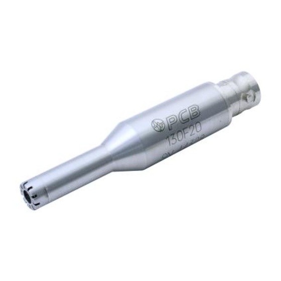
These microphones all have the same performance specifications but are fitted with different electrical connectors to make them suitable for differing applications. Model 130F20 features a BNC connector while Model 130F21 uses a 10-32 coaxial jack connector. Model 130F22 terminates in a SMB connector. These models are shown in Figure 1. -
Page 8: Installation
4.0 Installation There are many ways to mount the microphone, from simply placing the microphone in a clip to using a two-dimensional array stand. A diagram of an array configuration is provided in Figure 3. For installation of this type, remove the microphone from its package, connect the appropriate cable between the signal conditioner and the microphone, and connect a second cable between the signal conditioner and the data acquisition device. - Page 9 Calibration ratios for these types of devices are limited to 1:1. 5. See M anufacturer’s Specification Sheet for a detailed listing of performance specifications. 6. This certificate shall not be reproduced, except in full, without written approval from PCB Piezotronics, Inc 7. Calibrated per ACS-21.
- Page 10 Calibration ratios for these types of devices are limited to 1:1. 5. See M anufacturer’s Specification Sheet for a detailed listing of performance specifications. 6. This certificate shall not be reproduced, except in full, without written approval from PCB Piezotronics, Inc 7. Calibrated per ACS-21.
- Page 11 Calibration ratios for these types of devices are limited to 1:1. 5. See M anufacturer’s Specification Sheet for a detailed listing of performance specifications. 6. This certificate shall not be reproduced, except in full, without written approval from PCB Piezotronics, Inc 7. Calibrated per ACS-21.
-
Page 12: Service
All 130 series array microphones are designed for use in a free field environment. A free field environment is one without reflections. Anechoic rooms and outdoor spaces without structures are good examples of a free field environment. The free field response is the voltage response with respect to the pressure when exposed to a plane progressive sound wave. - Page 13 3425 Walden Avenue, Depew, NY 14043-2495 24-hour SensorLine : 716-684-0001 E-Mail: info@pcb.com Fax: 716-684-0987 Website: www.pcb.com Toll-free: 800-828-8840 ISO 9001 CERTIFIED AS9100 CERTIFIED In the interest of constant product improvement, specifications are subject to change without notice. Copyright PCB Group, Inc. 2016 ...
- Page 14 Model Number Revision: NR ICP® ELECTRET ARRAY MICROPHONE 130F20 ECN #: 45478 Performance ENGLISH OPTIONAL VERSIONS Nominal Microphone Diameter 1/4" 1/4" Optional versions have identical specifications and accessories as listed for the standard Frequency Response Characteristic(at 0° incidence) Free-Field Free-Field model except where noted below.
- Page 15 PCB Piezotronics Inc. claims proprietary rights in REVISIONS the information disclosed hereon. Neither it nor any reproduction thereof will be disclosed to others DESCRIPTION without the written consent of PCB Piezotronics Inc. RELEASED TO DRAFTING 45478 ELECTRICAL CONNECTOR BNC ELECTRICAL CONNECTOR 10-32 UNF-2A ELECTRICAL CONNECTOR SMB Ø...
Need help?
Do you have a question about the ICP 130F20 and is the answer not in the manual?
Questions and answers