Table of Contents
Advertisement
Quick Links
Advertisement
Table of Contents

Related Manuals for PCB Piezotronics 130B40


Summary of Contents for PCB Piezotronics 130B40
- Page 1 Model 130B40 ICP® ELECTRET SURFACE MICROPHONE Installation and Operating Manual For assistance with the operation of this product, contact PCB Piezotronics, Inc. Toll-free: 800-828-8840 24-hour SensorLine: 716-684-0001 Fax: 716-684-0987 E-mail: info@pcb.com Web: www.pcb.com...
- Page 2 Assistance is needed to safely operate equipment PCB Piezotronics is an ISO-9001 certified company whose Damage is visible or suspected calibration services are accredited by A2LA to ISO/IEC Equipment fails or malfunctions 17025, with full traceability to SI through N.I.S.T.
- Page 3 CAUTION Refers to hazards that could damage the instrument. NOTE Indicates tips, recommendations and important information. The notes simplify processes and contain additional information on particular operating steps. The following symbols may be found on the equipment described in this manual: This symbol on the unit indicates that high voltage may be present.
- Page 4 PCB工业监视和测量设备 - 中国RoHS2公布表 PCB Industrial Monitoring and Measuring Equipment - China RoHS 2 Disclosure Table 有害物质 镉 汞 铅 (Pb) 六价铬 (Cr(VI)) 多溴联苯 (PBB) 多溴二苯醚 (PBDE) 部件名称 (Hg) (Cd) 住房 PCB板 电气连接器 压电晶体 环氧 铁氟龙 电子 厚膜基板 电线 电缆 塑料 焊接...
- Page 5 Component Name Hazardous Substances Lead (Pb) Mercury (Hg) Cadmium (Cd) Chromium VI Polybrominated Polybrominated Compounds Biphenyls (PBB) Diphenyl Ethers (Cr(VI)) (PBDE) Housing PCB Board Electrical Connectors Piezoelectric Crystals Epoxy Teflon Electronics Thick Film Substrate Wires Cables Plastic Solder Copper Alloy/Brass This table is prepared in accordance with the provisions of SJ/T 11364.
-
Page 6: Table Of Contents
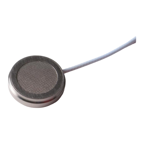
ICP microphones. This eliminates the need to purchase a separate preamplifier. The 130B40 Surface Microphone provides an extremely cost effective method for making general purpose measurements on flat and curved surfaces subjected to air movement. Typical applications include measuring wind-induced noise... -
Page 7: Powering
Each 130B series Microphone can measure audio frequencies ranging from 20 Hz to 20 kHz, with a broad dynamic range from 32 dBA to 142 dB. See Figure 2. The Microphone has a built- in TEDS (Transducer Electronics Data Sheet) chip that provides the unit’s sensitivity, calibration date, location and other data for traceability. -
Page 8: Installation And Operation
NOTE: Under no circumstances Figure 3 Readout should a voltage be supplied to an Signal microphone without a Conditioner Microphone current-regulating diode or equivalent electrical circuit. This may include ohmmeters, multi- meters and continuity testers. Damage to the built-in electronics resulting from the application of incorrect power, or the use of an unapproved power source is NOT... - Page 9 Top single-sided Moderate to heavy adhesive pad air flow Fairing Low air flow Microphone Base double-sided All conditions/ adhesive pad no air flow Figure 4: Methods of securing the Surface Microphone to its mounting surface Figure 5: One sided Adhesive Pad securing the Surface Microphone and Fairing in place - 4 -...
-
Page 10: Mounting Procedure
4.2. Mounting Procedure 1) Use the cleansing tissue (provided) to clean the location where the Surface Microphone will be mounted. (Alternatively, clean the surface with isopropanol or cleaning benzene.) 2) To attach the Surface Microphone using the double-sided adhesive pad (see Figure 6), peel off the protective paper on one side of the pad to expose its adhesive surface, apply firmly to the underside of the microphone, then peel off the protective paper on the other side of the pad to expose the other adhesive surface, and press it onto the clean surface. -
Page 11: Operation
4) To attach the single-sided adhesive pad (see Figure 8) when the Surface Microphone will be used in moderate to heavy air flow, peel off the protective paper to expose the pad’s adhesive surface and press it onto the Fairing as shown in Figure 5. Figure 8: Single sided adhesive pad 4.3. -
Page 12: Service
To perform the calibration, install the fairing pad onto the 130B40 Surface Microphone to help ensure a proper seal. Place the microphone and fairing pad on a flat, level surface. Turn the handheld calibrator upside down, and place the 1”... - Page 13 Model Number Revision: D ICP® ELECTRET SURFACE MICROPHONE 130B40 ECN #: 43176 Performance ENGLISH OPTIONAL VERSIONS Frequency Response Characteristic Pressure Pressure Optional versions have identical specifications and accessories as listed for the standard Frequency Response(+/-1 dB) 100 to 3000 Hz 100 to 3000 Hz model except where noted below.
Need help?
Do you have a question about the 130B40 and is the answer not in the manual?
Questions and answers