Advertisement
- 1 SAFETY SYMBOLS
- 2 SPECIFICATIONS
- 3 PACKAGE DESCRIPTION
- 4 ASSEMBLY
-
5
OPERATION
- 5.1 APPLICATIONS
- 5.2 ATTACHING/DETACHING THE BATTERY
- 5.3 MOUNTING THE SHOULDER STRAP AND HOLDING THE MACHINE
- 5.4 STARTING/STOPPING THE MACHINE
- 5.5 CHANGING SPEED MODE
- 5.6 BATTERY-STATUS INDICATOR AND SPEED INDICATOR
- 5.7 BLUETOOTH WIRELESS TECHNOLOGY
- 5.8 USING WITH LINE TRIMMER HEAD
- 5.9 USING WITH BRUSH CUTTER HEAD
- 6 MAINTENANCE
- 7 TROUBLESHOOTING
- 8 Documents / Resources
SAFETY SYMBOLS

Residual risk! People with electronic devices, such as pacemakers, should consult their physician(s) before using this product. Operation of electrical equipment in close proximity to a heart pacemaker could cause interference or failure of the pacemaker.
The operation of any machines can result in foreign objects being thrown into your eyes, which can result in severe eye damage. Before beginning machine operation, always wear safety goggles or safety glasses with side shields and a full face shield when needed. We recommend a Wide Vision Safety Mask for use over eyeglasses or standard safety glasses with side shields.
 | Safety Alert |  | Read & Understand Operator's Manual |
 | Wear Eye Protection |  | Wear Ear Protection |
 | Wear Head Protection |  | Wear Hand Protection |
 | Wear Slip-resistant Footwear |  | Beware of thrown objects |
 | Beware of Blade Thrust |  | Disconnect battery before maintenance |
 | The distance between the machine and bystanders shall be at least 15 m. |  | Cutting width-The Max. cutting width of line trimmer Waste electrical products should not be |
 | Line diameter-The Diameter of the nylon cutting line |  | Waste electrical products should not be disposed of with household waste. Take to an authorized recycler. |
 | Guaranteed sound power level. Noise emission to the environment according to the European community's Directive. |  | The product complies with the applicable European directives. |
 | Bluetooth ® |  | UK Conformity Assessed. |
| n0 | Maximum Speed | IPX5 | Ingress Protection Degree |
 | Direct Current | V | Voltage |
| kg | Kilogram | .../min | Revolutions or reciprocation per minute |
| mm | Millimeter | cm | Centimeter |
 NOTE: The Bluetooth ® word mark and logos are registered trademarks owned by Bluetooth SIG, inc. and any use of such marks by EGO is under license.
SPECIFICATIONS
| Voltage | 56 V  | |
| n0 | Low: 3500 /min Medium: 4500 /min High: 5200 /min | |
| Cutting Mechanism | Bump Head | |
| Cutting Line Type | 2.7 mm nylon twist line | |
| Cutting Width | 45 cm | |
| Recommended Operating Temperature | 0°C - 40°C | |
| Recommended Storage Temperature | -20°C - 70°C | |
| Optimum Charging Temperature | 5°C - 40°C | |
| Weight (without battery pack) | 4.1 kg | |
| Measured sound power level LWA | 95 dB(A) K=1.6 dB(A) | |
| Sound pressure level at operator's ear LPA | 82 dB(A) K=3 dB(A) | |
| Guaranteed sound power level LWA (measured according to 2000/14/EC) | 96 dB(A) | |
| Valuation of vibration ah: | Loop Handle | 1.7 m/s2 K=1.5 m/s2 |
| Rear handle | 1.2 m/s2 K=1.5 m/s2 | |
- The declared vibration total value has been measured in accordance with a standard test method and may be used for comparing one machine with another;
- The declared vibration total value may also be used in a preliminary assessment of exposure.
NOTICE: The vibration emission during actual use of the machine can differ from the declared value in which the machine is used; In order to protect the operator, user should wear gloves and ear protectors in the actual conditions of use.
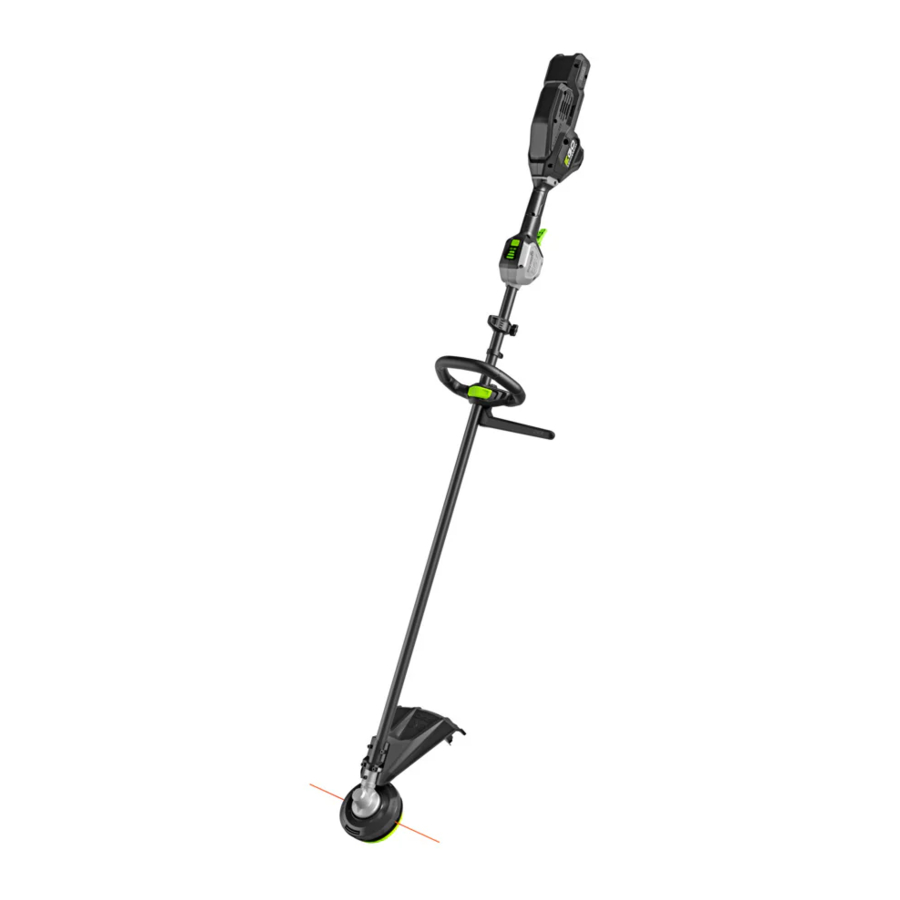
PACKAGE DESCRIPTION
KNOW YOUR LINE TRIMMER (Fig. A1)

- Speed Indicator
- Bluetooth® Indicator
- Speed Mode Button
- Battery-status Indicator
- Rear Handle
- Carrying Eyelet
- Loop Handle
- Shoulder Strap
- Shaft
- Trimmer Line
- Release Tab
- Trimmer Head (Bump head)
- Line-cutting Blade
- Line Trimmer Guard
- Threshold Ring
- Lock-off Lever
- Trigger Switch
- Battery-release Button
- Latch
- Electric Contacts
- Battery Ejector
- Safety Barrier Bar (only for use with brush cutter head)
- Outer Flange (only for use with brush cutter head)
- Nut (only for use with brush cutter head)
- Hex Key
- Sealing Bolt (2)
- Brush Cutter Guard *
- 3-tooth Blade *
- Blade Sheath *
* SOLD SEPARATELY
ASSEMBLY
If any parts are damaged or missing, do not operate this product until the parts are replaced. Use of this product with damaged or missing parts could result in serious personal injury.
Do not attempt to modify this product or create accessories not recommended for use with this line trimmer. Any such alteration or modification is misuse and could result in a hazardous condition leading to possible serious personal injury.
To prevent accidental starting that could cause serious personal injury, always remove the battery pack from the machine when assembling parts.
When the machine is equipped with brush cutter head, the safety barrier bar shall be mounted.
MOUNTING THE GUARD


Always wear gloves when mounting or replacing the guard. Take care of the blade on the guard and protect your hand from cutting.
Never operate the machine without the guard firmly in place. The guard must always be on the machine to protect the user! When the guard is fixed, never attempt to remove or adjust the guard, if a replacement is needed, it should be performed by a qualified service technician!
NOTICE: There are two kinds of guards compatible with this machine. Only the guard with icon ![]() can be used with line trimmer head and must NOT be used with brush cutter head. Be careful to choose the correct guard when using the machine.
can be used with line trimmer head and must NOT be used with brush cutter head. Be careful to choose the correct guard when using the machine.
NOTICE: The brush cutter guard is sold separately.
Loosen and remove the two bolts from the guard, align the guard mounting holes with the assembly holes and then lock the guard onto the shaft base with the two bolts, together with two spring washers.
Make sure the guard is fixed according to Fig. B1 & B2, any reverse fixing will cause great danger!
MOUNTING AND ADJUSTING THE LOOP HANDLE
- Stop the motor and remove the battery pack from the machine, if installed.
- Loosen the wing nut to separate the adjustable loop handle (Fig. C).


NOTICE: Must install the safety barrier bar onto the loop handle when the machine is equipped with brush cutter head.
| C-1 | Loop handle | C-4 | Quick-release Lever |
| C-2 | Clamping block | C-5 | Safety barrier bar (only for use with brush cutter head) |
| C-3 | Wing nut |
- Push the loop handle onto the shaft between the threshold ring and the warning label (Fig. D1).

- Insert the clamping block into the handle slot (Fig. D2).

- Align the recessed part in the barrier bar with the protruded part on the loop handle, press the barrier bar onto the loop handle (Fig. D3).

- Mount the quick-release lever and tighten the wing nut. Make sure that the loop handle is positioned upwards and points toward the top of the rear handle (Fig. D4).

- Pull the quick-release lever up to move/rotate the loop handle to a comfortable operating position (Fig. D5).

- Fold the quick-release lever to secure the loop handle in place (Fig. D6).


Never operate the machine without the loop handle firmly in place.
REPLACE THE TRIMMER HEAD WITH THE BRUSH CUTTER HEAD
- Remove the battery pack from the machine
- Rotate the trimmer head to align the slot in the flange with the shaft-locking hole in the gear case and insert a stabilizer into the hole (Fig. E1).

- Rotate the trimmer head CLOCKWISE to remove it from the motor shaft (Fig. E1, E2).

- The blade is shipped with a sheath. Before mounting the blade onto the brush cutter, the sheath should be removed from the hook on the sheath (Fig. E3).

![information]() NOTICE: To protect against injury, you have to wear gloves prior to any operation with the 3-tooth blade.
NOTICE: To protect against injury, you have to wear gloves prior to any operation with the 3-tooth blade. - Mount the inner flange and flange cover into its place, if they had separated from the shaft (Fig. E4).

- Mount the blade onto the motor shaft, ensuring that the surface of the blade is flush with the surface of the inner flange bulge. Mount the outer flange and the nut (Fig. E5). Finger-tighten the nut COUNTERCLOCKWISE.

- Position the gear case against a solid surface for support. With one hand hold the brush cutter shaft and the other hand grasp a 16 mm socket wrench (not included) to tighten the nut COUNTERCLOCKWISE (Fig. E6).

- Remove the line trimmer guard by loosening the two bolts with washers (Fig. E7).

- Install the brush cutter guard (not included) with the two bolts and washers from the line trimmer, the same way as line trimmer guard (Fig. E8).


NOTICE: When the machine is equipped with the brush cutter head, be carefully to choose the correct guard.
OPERATION
Do not allow familiarity with this product to make you careless. Remember that a careless fraction of a second is sufficient to inflict serious injury.
Always wear eye protection, along with hearing protection. Failure to do so could result in objects being thrown into your eyes and other possible serious injuries.
Do not use any attachments or accessories not recommended by the manufacturer of this product. The use of attachments or accessories not recommended can result in serious personal injury.
To prevent serious personal injury, remove the battery pack from the machine before servicing, cleaning, changing attachments or removing material from the unit.
APPLICATIONS
You may use this product for the purposes listed below:
Trimming: used for removing grass and weeds up against walls, fences, trees and borders.
Cutting: used for cutting the grass that is difficult to reach using a normal mower.
NOTICE: The machine is to be used only for its prescribed purposes. Any other use is deemed to be a case of misuse.
ATTACHING/DETACHING THE BATTERY
Use only with EGO's battery packs and chargers listed in Fig. A2.

Fully charge before first use.
To Attach (Fig. F1)

Align the battery ribs with the mounting slots in the machine battery port and slide the battery pack until it snaps into position.
To Detach (Fig. F2)

Depress the battery-release button and the battery pack will disengage from the latch.
Always be aware for the location of your feet, children, or pets when pressing the battery-release button. Serious injury could result in if the battery pack falls. NEVER remove the battery pack at a high location.
MOUNTING THE SHOULDER STRAP AND HOLDING THE MACHINE
Depress the carabiner to open it and attach it onto the carrying eyelet (Fig. H1).

For safe and better operation, put on the shoulder strap across the shoulder as Fig. H2. Adjust the shoulder strap in a comfortable operating position. Hold the machine with both hands: One hand on the rear handle and the other hand on the loop handle. The trimmer head should be parallel to the ground so that it easily contacts the material to be cut without the operator having to bend over.

There are two ways to release the strap. Take it away from your shoulder directly (Fig. H3) or press the hook of the strap and take it apart from the carrying eyelet fixed on the shaft (Fig. H4).

The shoulder strap is also a quick release mechanism in a hazardous situation. When an emergency occurs, take it off from your shoulder immediately, no matter what way the strap is in.
When wearing the strap, no other wearable should interfere with the release and removal of the strap.
ou should not use the single-shoulder strap and double-shoulder strap simultaneously.
STARTING/STOPPING THE MACHINE
(Fig. J)
To Start
- Move the lock-off lever forward and then press the trigger switch to start.
- Different pressure on the trigger results in variable rotating speed of the cutting unit. Adjust the speed to suit the task at hand.
NOTICE: The motor starts only when the lock-off lever is moved forward and the trigger switch is depressed at the same time.
To Stop
Move the machine away from the cutting area and release the trigger switch to stop it.
Always remove the battery pack from the machine during work breaks and after finishing work.

| J-1 | Lock-off Lever | J-2 | Trigger Switch |
CHANGING SPEED MODE
The machine features three speed modes. Every time press the speed mode switch, the speed mode will change.
The speed indicator will display the active speed status: one light for low speed, two lights for medium speed, three lights for high speed. The low speed mode provides better control of the machine and longer operating time per charge.
NOTICE: The speed mode can be set before the machine is turned on OR during operation.
| Indicator Lights | Meaning | ||
| Battery-status indicator | Solid green |  | Battery charge level of 20% to 100% |
| Flashing green |  | Battery charge level of 10% to 20% | |
| Solid red |  | Battery charge level of less than 10% | |
| Flashing red |  | The battery pack is nearly depleted and needs to be charged immediately. | |
| Solid orange |  | The battery pack is overheated. Cool the battery pack until the temperature drops below 67°C. See " Battery High-Temperature Protection " below | |
| Flashing red/ green alternately |  | The battery pack electronics error. Replace the battery pack or contact EGO customer service center. See " Battery Electronics Error Protection " below. | |
| Speed indicator (the illustration shows the high speed) | Solid green |  | The machine is working properly. |
| Solid orange |  | The machine is overheated. Cool the machine until the temperature drops below 80°C. See "Machine High-Temperature Protection " below. | |
| Flashing orange |  | The machine is overloaded. See "Machine Overload Protection" below. | |
When the machine is re-started after a break, the speed mode will return to the previous speed.

| K-1 | Speed Indicator | K-3 | Speed Mode Button |
| K-2 | Bluetooth® Indicator | K-4 | Battery-status Indicator |
BATTERY-STATUS INDICATOR AND SPEED INDICATOR
(FIG. K)
The battery-status indicator shows the charge level and the working status of the battery pack, and the speed indicator shows the working status of the machine as shown in the chart below. The battery-status indicator and the speed indicator will illuminate when the machine is started OR the speed mode button is pressed.
Battery High-Temperature Protection
If the battery temperature exceeds 70°C during operation, the temperature-protection circuit will immediately shut off the machine to protect the battery pack from overheating damage. The battery-status indicator will glow solid orange. Release the trigger and wait until the overheated battery cools down and the indicator turns green, then restart the machine.
Battery Electronics Error Protection
When the battery pack electronics error occurs, the battery-status indictor will flash red/green alternately and the machine will shut off in 3 seconds. Replace the battery pack or contact EGO customer service center.
Machine Overload Protection
This machine has built-in overload circuit protection. When the machine is overloaded, the motor will stop and the speed indicator will flash orange. Remove the battery pack from the machine, then reattach the battery pack and restart the machine. Decrease the load on the machine, avoid too long or oversize cutting line or cutting on the heavy/woody shrubs.
Machine High-Temperature Protection
If the machine temperature exceeds 90°C during operation, the temperature-protection circuit will immediately shut off the machine from overheating damage. The speed indicator will glow solid orange. Release the trigger and wait until the overheated machine cools down and the speed indicator turns green, then restart the machine.
BLUETOOTH® WIRELESS TECHNOLOGY
Products with built-in Bluetooth® wireless technology can connect to EGO Connect services via your mobile device or EGO Bluetooth® Gateway device. For information or our full range of connected products and services, including connection instructions, please scan QR Code below or visit www.egopowerplus.eu/connect.
The Bluetooth® symbol ![]() will light up when machine is connected.
will light up when machine is connected.

USING WITH LINE TRIMMER HEAD
To avoid serious personal injury, wear goggles or safety glasses at all times when operating this unit. Wear a face mask or dust mask in dusty locations.
Clear the area to be cut before each use. Remove all objects, such as rocks, broken glass, nails, wire, or line that can be thrown or become entangled in the cutting attachment. Clear the area of children, bystanders, and pets. At a minimum, keep all children, bystanders and pets at least 15m away; there still may be risk to bystanders from thrown objects. Bystanders should be encouraged to wear eye protection. If you are approached, stop the motor and cutting attachment immediately.
Before each use, check for damage/worn parts
Check the bump head, guard and loop handle and replace the parts that are cracked, warped, bent, or damaged in any away.
The line-cutting blade on the edge of the guard can dull over time. It is recommended that you periodically sharpen it with a file or replace it with a new blade.
After each use, clean the trimmer.

Obstructions in the vents will prevent the air from flowing into the motor housing and result in overheating or damaged of the motor.
- Use only mild soap and a damp cloth to clean the machine. Never let any liquid get inside the machine; never immerse any part of the machine into a liquid.
- Keep air vents in the motor housing from debris at all times.
Never use water for cleaning your trimmer. Avoid using solvents when cleaning plastic parts. Most plastics are susceptible to damage from various types of commercial solvents. Use clean cloths to remove dirt, dust, oil, grease, etc.
Check for blockage of the trimmer head
- To prevent blockage, keep the trimmer head clean. Remove grass clippings, leaves, dirt and any other accumulated debris before and after each use.
- When blockage happens, stop the line trimmer and remove the battery, then remove any grass that may have wrapped itself around the motor shaft or trimmer head.
Adjusting cutting line length
The trimmer head allows the operator to release more cutting line without stopping the motor. As line becomes frayed or worn, additional line can be released by lightly tapping the bump head on the ground while operating the trimmer.

NOTICE: Line release will become more difficult if the cutting line becomes too short.
Do not remove or alter the line cutting blade assembly. Excessive line length will cause the motor to overheat and may result in serious personal injury.
Line replacement
NOTICE: Always use the recommended nylon cutting line with a diameter that does not exceed 2.7 mm. Using line other than that specified may cause the line trimmer to overheat or become damaged.
Never use metal-reinforced line, wire, or rope, etc. These can break off and become dangerous projectiles.
- Remove the battery pack from the line trimmer.
- Cut 6 m long cutting line, insert the line into the mounting hole inside the eyelet (Fig. M1). Push and pull the line from the other side until equal amounts of line appear on both sides of the spool.

- Press, while rotating the lower cover assembly in the arrow direction, to wind the line onto the spool until approximately 15 cm of line is showing on each side (Fig. M2).

- Push the lower cover assembly down while pulling on the lines to manually advance the line and to check for proper assembly of the trimmer head.


Reloading the cutting line
When the cutting line breaks from the line outlet or the cutting line is not released when the trimmer head is tapped, follow the below steps:
- Press the release tabs on the upper cover and remove the lower cover assembly by pulling it straight out (Fig. N1).

- Remove the cutting line from the spool.
![warning]() With one hand holding the trimmer, use another hand to grasp the lower cover assembly and align the tabs on the upper cover with the slots in the lower cover assembly (Fig. N2); Press the lower cover assembly until it snaps into place with a distinct click sound.
With one hand holding the trimmer, use another hand to grasp the lower cover assembly and align the tabs on the upper cover with the slots in the lower cover assembly (Fig. N2); Press the lower cover assembly until it snaps into place with a distinct click sound.
![]()
- Follow the instructions in "Line replacement" to reload the cutting line.


Tips for best trimming results
- The correct angle for the cutting attachment is parallel to the ground.
- Do not force the trimmer. Allow the very tip of the line to do the cutting (especially along walls). Cutting with more than the tip will reduce cutting efficiency and may overload the motor.
- The cutting height is determined by the distance of the cutting line from the lawn surface.
- Grass over 8 inches (20 cm) should be cut by working from top to the bottom in small increments to avoid premature line wear or motor drag.
- Slowly move the trimmer into and out of the area being cut, maintaining the cutting head position at the desired cutting height. This movement can be either a forward-backward motion or a side-to-side motion. Cutting shorter lengths produces best results.
- Avoid trimming when grass and weeds are wet.
Wire and picket fences can cause extra string wear or breakage. Stone and brick walls, curbs, and wood may wear strings rapidly.
Avoid trees and shrubs. Tree bark, wood moldings, siding, and fence posts can easily be damaged by the strings.
USING WITH BRUSH CUTTER HEAD
To cut wild growth and scrub, lower the rotating 3-tooth blade down onto the growth to achieve a chopping effect. Use the brush cutter like a scythe (sweep it to the right and left) at ground level. Do not use the cutting unit above waist height.
The higher the cutting unit is off the ground, the greater the risk of injury from cuttings being thrown sideways.
When cutting young stands or other woody materials up to 2cm in diameter, use the left side of the blade to avoid blade thrust situations. Do not attempt to cut woody material with a larger diameter, since the blade may catch or jerk the brush cutter forward. This may cause damage to the blade or the brush cutter or loss of control of the brush cutter, resulting personal injury.
Improper use of a blade may cause it to crack, chip, or shatter. Thrown parts may seriously injure the operator or bystander. To reduce the risk of personal injury, it is essential to take the following precautions:
- Avoid contact with hard or solid foreign objects such as stones, rocks or pieces of metal.
- Never cut wood or shrubs with a stem diameter of more than 2 cm.
- Inspect the blade at a regular short interval for signs of damage. Do not continue working with a damaged blade.
- Re-sharpen the blade regularly (when it has dulled noticeably) and have it balanced if necessary (performed by a qualified service technician).
Tips for best brush-cutting
- Always hold brush cutter on your right side with both hands when operating. Use a firm grip on both handles.
- Maintain your grip and balance on both feet. Position yourself so that you will not be drawn off balance by the kickback reaction of the cutting blade.
- Inspect and clear the area of any hidden objects such as glass, rocks, concrete, fencing, wire, wood, metal, etc., which can be thrown or entangled in the blade.
- Never use blades near sidewalks, fencing, posts, buildings or other immovable objects.
- Never use a blade after hitting a hard object without first inspecting it for damage. Do not use if any damage is detected.
- Use the unit for cutting from the right to the left in a broad sweeping action from side to side.
- Use only the EGOTM blade. Using any other brand blade with this brush cutter could result in serious personal injury.
MAINTENANCE
Before inspecting, cleaning or servicing the unit, stop the motor, wait for all moving parts to stop, and remove the battery pack. Failure to follow these instructions can result in serious personal injury or property damage.
When servicing, use only identical replacement parts. Use of any other parts may create a hazard or cause product damage. To ensure safety and reliability, all repairs should be performed by a qualified service technician.
CLEAN THE MACHINE
- Clean the unit using a damp cloth with a mild detergent.
- Do not use any strong detergents on the plastic housing or the handle. They can be damaged by certain aromatic oils, such as pine and lemon, and by solvents such as kerosene. Moisture can also cause a shock hazard. Wipe off any moisture with a soft dry cloth.
LUBRICATE THE GEAR CASES
For best operation and longer lifetime, lubricate the gear CASES with a special grease (4-5 ml each time) after every 50 hours operation.
The special grease should meet the following requirements:
- Belong to DIN51818: NLGI-1 cone penetration degree.
- Ester base grease.
- Excellent low-temperature startup, EP, mechanical shearing, abrasion resistance and oxidative stability properties.
- Operation temperature must contain -40~180°C.
Remove the battery and the sealing bolts. Lubricating the gear cases through the oil-hole.
STORING THE MACHINE
- Remove the battery pack from the machine when it is not in use.
- Clean the machine thoroughly before storing it.
- Store the unit in a dry, well-ventilated area, locked-up or up high, out of the reach of children. Do not store the machine on or adjacent to fertilizers, gasoline, or other chemicals.
- Use of the blade sheath onto the 3-tooth blade during transport and storage.
TROUBLESHOOTING
| PROBLEM | CAUSE | SOLUTION |
Fail to start | The battery pack is not attached to the line trimmer. | Attach the battery pack to the line trimmer. |
| No electrical contact between the machine and battery. | Reinsert the battery pack. | |
| The battery pack is depleted. | Charge the battery pack. | |
| The lock-off lever and trigger switch are not depressed simultaneously. | Move the lock-off lever forward, then depress the trigger to turn on the machine. | |
The machine stops working while cutting | Heavy cutting line is used. | Use recommended nylon cutting line with diameter no greater than 2.7 mm. |
| The motor is overloaded. | The machine will recover when the load is removed. For continuous working, reduce the load of the machine. | |
| The battery pack or machine is too hot. | Allow the battery pack or machine to cool until the temperature drops below 67°C. | |
| The battery pack is disconnected from the machine. | Re-install the battery to the machine. | |
| The battery pack is depleted. | Charge the battery pack. | |
The cutting line can't be released(only using with trimmer head) | The motor shaft or trimmer head is wound with grass. | Stop the trimmer, remove the battery and remove the grass from the motor shaft and trimmer head. |
| There is no enough line in the trimmer head. | Remove the battery and replace the cutting line; follow the section "LINE REPLACEMENT" in this manual. | |
| The trimmer head is dirty. | Remove the battery and clean the lower cover assembly, spool and upper cover. | |
| Line is tangled in the trimmer head. | Remove the battery, remove the line from the spool and rewind; follow the section "LINE REPLACEMENT" in this manual. | |
| The line is too short. | Remove the battery and pull the line while alternately pressing down on and releasing the trimmer head. | |
Grass wraps around trimmer head and motor housing | Cutting tall grass at ground level. | Cut out the weeds into several sections from top to ground level. |
Please visit the website egopowerplus.eu for full terms and conditions of the EGO Warranty policy.
Documents / Resources
References
Download manual
Here you can download full pdf version of manual, it may contain additional safety instructions, warranty information, FCC rules, etc.
Advertisement


Need help?
Do you have a question about the STX4500 and is the answer not in the manual?
Questions and answers