Advertisement
Quick Links
Advertisement

Related Manuals for Cuisinart GAS2556AF


Summary of Contents for Cuisinart GAS2556AF
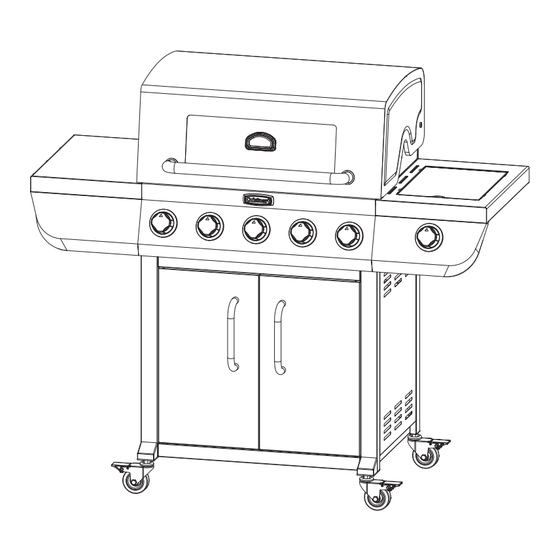
- Page 1 5 Burner Gas Grill ASSEMBLY IN STRUC TIONS Model GAS2556AF...
- Page 2 READ ALL SAFETY WARNINGS & ASSEMBLY INSTRUCTIONS CAREFULLY BEFORE ASSEMBLING OR OPERATING YOUR GRILL. WE RECOMMEND TWO PEOPLE WORK TOGETHER WHEN AS SEM BLING THIS UNIT. The following tools are required to assemble this Cuisinart 5 Burner Gas Grill: • Phillips Screwdriver PARTS LIST:...
- Page 4 Step 1 • Remove two Remove screws and door two screws spacers from each door handle • Attach door handles doors in door frame using four screws. Step 2 • Remove two screws from door frame . Set aside for later use. Remove two screws...
- Page 5 Loosen three Step 3 screws • Loosen three screws on door frame • Attach right side panel to door frame over keyholes and tighten screws. • Remove one screw and set aside. Remove one screw Loosen three Step 4 screws •...
- Page 6 Step 5 • Loosen four screws on cart side panels. • Attach back panel to cart over keyholes and partially tighten screws. • Do not fully tighten screws at this time. Step 6 Remove 2 screws • Remove two screws from cart base...
- Page 7 Step 7 • Attach cart base to cart using two pre-attached screws and two screws removed from Steps 3 and • Tighten all screws on cart base Step 8 • Lock casters • Attach casters to legs Unlocked Locked...
- Page 8 Step 9 • Attach back panel using two screws removed from Step • Tighten the four screws from Step 4. Step 10 • Attach tank block to cart using two pre- attached screws.
- Page 9 Step 11 • Attach door stopper cart base using two pre-attached screws. Step 12 • Attach one griddle bracket to right side panel using two pre-attached screws. • Attach the other griddle bracket to door frame using two screws removed in Step 2. •...
- Page 10 Step 13 • Attach bezel and temperature gauge to hood using pre-attached wing nut and washer. Left Side Step 14 LEFT SIDE • Loosen six Remove screws. Brackets • Remove protective bracket. Right Side • Remove 1 screw. RIGHT SIDE •...
- Page 11 Step 15 • Place grill body assembly on cart. Step 16 • Loosen screws and rotate brackets upwards. • Tighten screws. • Repeat on both sides of grill body.
- Page 12 Step 17 LEFT SIDE RIGHT SIDE TABLE TABLE • Remove two screws and washers and set aside. Remove screws washers Step 18 Loosen four screws • Loosen 4 screws. • Attach left and right front control panels over keyholes. Align •...
- Page 13 Step 19 • Attach left side table over keyholes. • Do not tighten screws at this point in time. Step 20 • Install screw. (screw was removed in Step • Do not tighten screw at this time. Install screw...
- Page 14 Step 21 • Install screw and washer (screw and washer were removed in Step 17). Do not tighten screw at this time. • Make sure panels are aligned. • Tighten 6 screws from Steps 19 through 21. Align Panels Step 22 •...
- Page 15 Step 23 • Install screw. (screw was removed in Step 14) • Do not tighten screw at this time. Install screw Step 24 • Install screw and washer (screw and washer were removed in Step 17). Do not tighten screw at this time.
- Page 16 Step 25 • Remove wing nut SIDE BURNER and remove burner. VALVE Install side burner valve in control panel. BURNER VENTURI WING • Slide valve downward and tighten two screws to lock into place (see diagram Step VALVE NOZZLE • Install burner and make sure burner venturi fi ts over...
- Page 17 Step 27 • Attach wire clip to side burner. SIDE BURNER SIDE BURNER VALVE WIRE CLIP Step 28 • Attach ignitor wire to electrode. ELECTRODE IGNITER WIRE...
- Page 18 Step 29 • Install side burner SIDE BURNER grate GRATE Step 30 • Remove two screws from grease tray handle. • Attach grease tray hadle to outside using two screws. • Tighten screws.
- Page 19 Step 31 GREASE TRAY • Install grease tray and grease through back of grill. GREASE CUP Step 32 WARMING RACK • Install heat tents , cooking grates and warming COOKING GRATES rack HEAT TENTS...
- Page 20 Model GAS2556AF Assembled ©2021 The Boltz Group LLC OM2556AF Assembly Instructions for Model Carrollton, Texas 75006 U.S.A. 0821 GAS2556AF...
Need help?
Do you have a question about the GAS2556AF and is the answer not in the manual?
Questions and answers